How to Use Resistive Touch Display : Examples, Pinouts, and Specs
Introduction
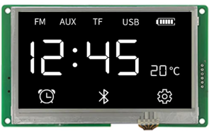
The DWIN HMI Resistive Touch Display is an electronic component that allows users to interact with a system through touch inputs. It operates on the principle of resistive touch technology, where pressure applied to the screen causes two conductive layers to make contact, thus registering a touch event. This type of display is commonly used in a variety of applications, including industrial control panels, ATMs, point-of-sale systems, and medical devices due to its durability and cost-effectiveness.
Explore Projects Built with Resistive Touch Display
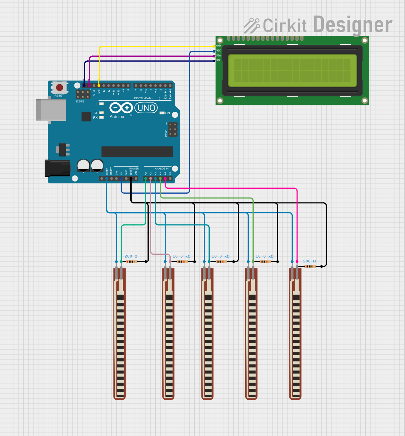
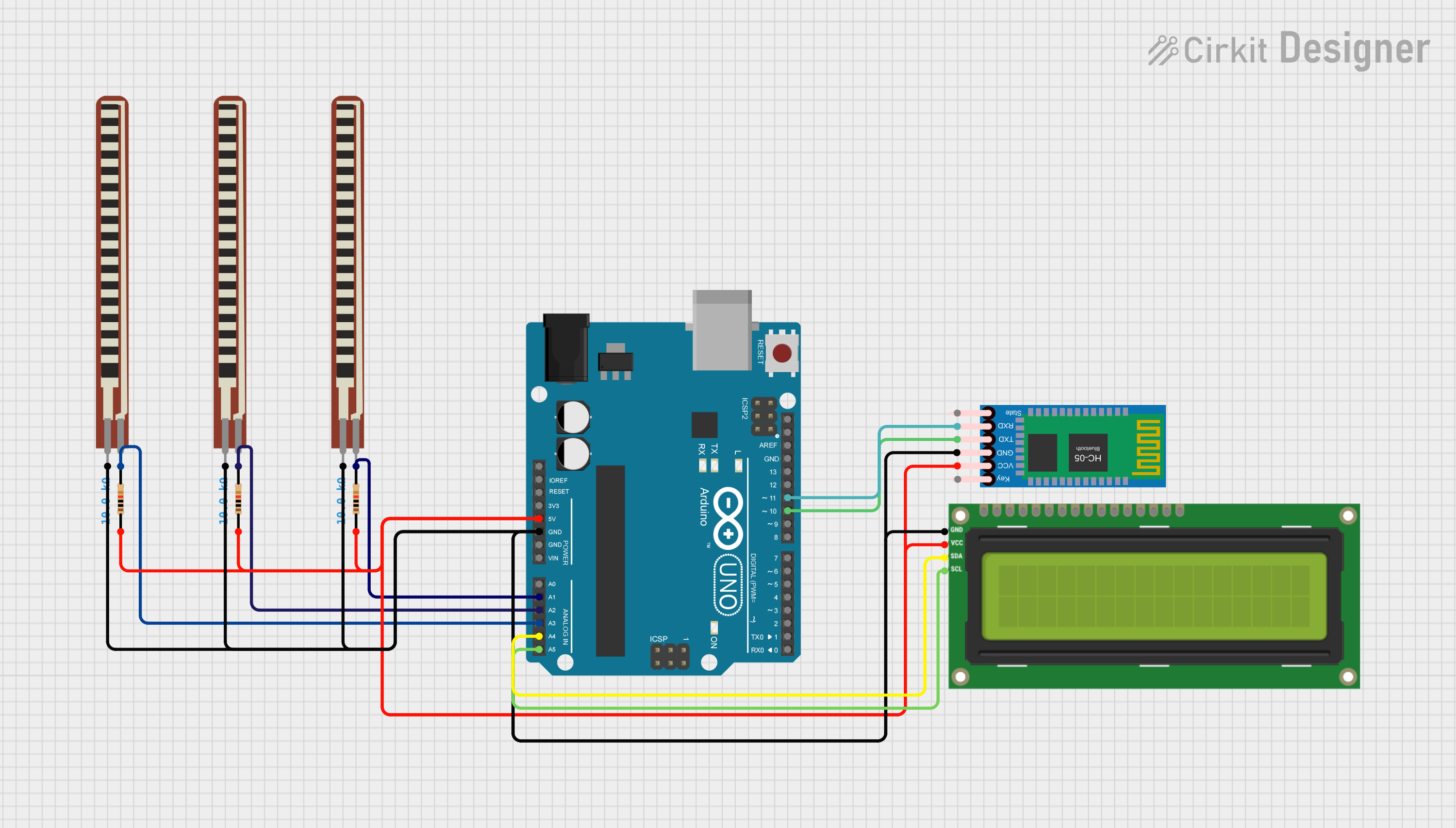
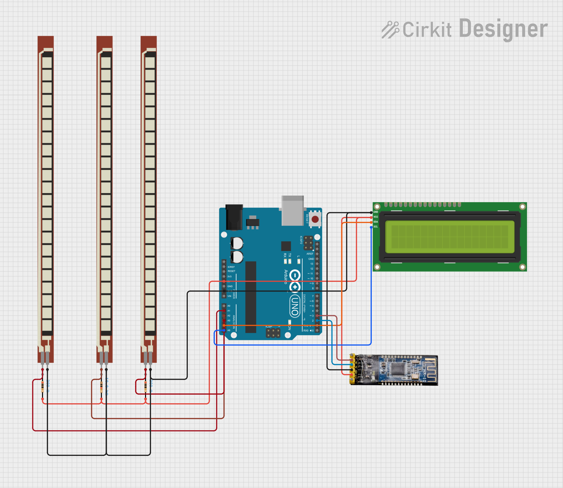
Explore Projects Built with Resistive Touch Display
Technical Specifications
General Features
- Display Type: Resistive Touchscreen
- Manufacturer: DWIN
- Part ID: HMI
- Screen Size: Varies (common sizes include 3.5", 4.3", 7", etc.)
- Resolution: Varies with size (e.g., 320x240, 480x272, 800x480 pixels)
- Interface: Typically includes UART, SPI, or parallel interfaces
Electrical Characteristics
- Operating Voltage: 3.3V to 5V DC
- Typical Current Consumption: Depends on size and backlight setting
Pin Configuration and Descriptions
| Pin Number | Name | Description |
|---|---|---|
| 1 | VCC | Power supply (3.3V-5V) |
| 2 | GND | Ground connection |
| 3 | TX | Transmit data (to MCU) |
| 4 | RX | Receive data (from MCU) |
| 5 | RST | Reset signal |
| 6 | INT | Interrupt signal (touch event) |
| ... | ... | Additional pins may include SPI or parallel interface signals |
Note: The exact pinout can vary based on the specific model of the DWIN HMI display. Always refer to the manufacturer's datasheet for accurate pin assignments.
Usage Instructions
Integration with a Circuit
- Power Supply: Connect the VCC pin to a 3.3V or 5V power source and the GND pin to the system ground.
- Data Communication: Connect the TX and RX pins to the corresponding RX and TX pins of the microcontroller (cross-connection).
- Reset: The RST pin can be connected to a microcontroller pin for software reset functionality.
- Touch Event: The INT pin can be connected to an interrupt-capable pin on the microcontroller to detect touch events.
Best Practices
- Use a voltage regulator if the power supply is not stable or clean.
- Implement proper ESD protection when handling the display.
- Calibrate the touch screen according to the manufacturer's instructions for accurate touch detection.
- Avoid applying excessive force to the screen to prevent damage to the resistive layers.
Troubleshooting and FAQs
Common Issues
- Touch Not Registering: Ensure the INT pin is properly connected and configured to detect interrupts. Check for proper calibration of the touch screen.
- Display Not Powering On: Verify the power supply connections and voltages. Check for any shorts or open circuits.
- Garbled Data on Screen: Confirm that the communication protocol and baud rate settings match between the display and the microcontroller.
FAQs
Q: Can the display operate at both 3.3V and 5V? A: Yes, the display is typically designed to work within a range of 3.3V to 5V. However, always check the datasheet for the specific model you are using.
Q: How do I calibrate the touch screen? A: Calibration procedures can vary. Refer to the manufacturer's documentation for calibration instructions specific to your model.
Q: Is the resistive touch display compatible with Arduino UNO? A: Yes, it can be connected to an Arduino UNO using UART or SPI, depending on the model.
Example Arduino Code
#include <SoftwareSerial.h>

// Define the RX and TX pins connected to the display
#define DISPLAY_RX 10
#define DISPLAY_TX 11

// Initialize the software serial port
SoftwareSerial displaySerial(DISPLAY_RX, DISPLAY_TX);

void setup() {
  // Start the serial communication
  displaySerial.begin(9600);
  Serial.begin(9600);
}

void loop() {
  // Check if the display has sent any data
  if (displaySerial.available()) {
    // Read the data from the display
    String touchData = displaySerial.readString();
    // Process the touch data (this will depend on your application)
    Serial.println(touchData);
  }

  // Add your code to handle other tasks
}
Note: The above code is a simple example to demonstrate communication with the display. The actual implementation will depend on the specific commands and protocols used by the DWIN HMI display model you have.
Remember to consult the DWIN HMI datasheet and user manual for detailed information on command sets and additional features.