How to Use xt60: Examples, Pinouts, and Specs
Introduction
The XT60 is a high-current connector widely used in RC (radio-controlled) applications, drones, electric vehicles, and other high-power systems. It is designed to handle up to 60A of continuous current, making it ideal for applications requiring reliable and efficient power delivery. The XT60 features a secure, polarized design that prevents reverse connections, ensuring safe and consistent operation. Its robust construction and gold-plated contacts provide low resistance and long-term durability.
Explore Projects Built with xt60


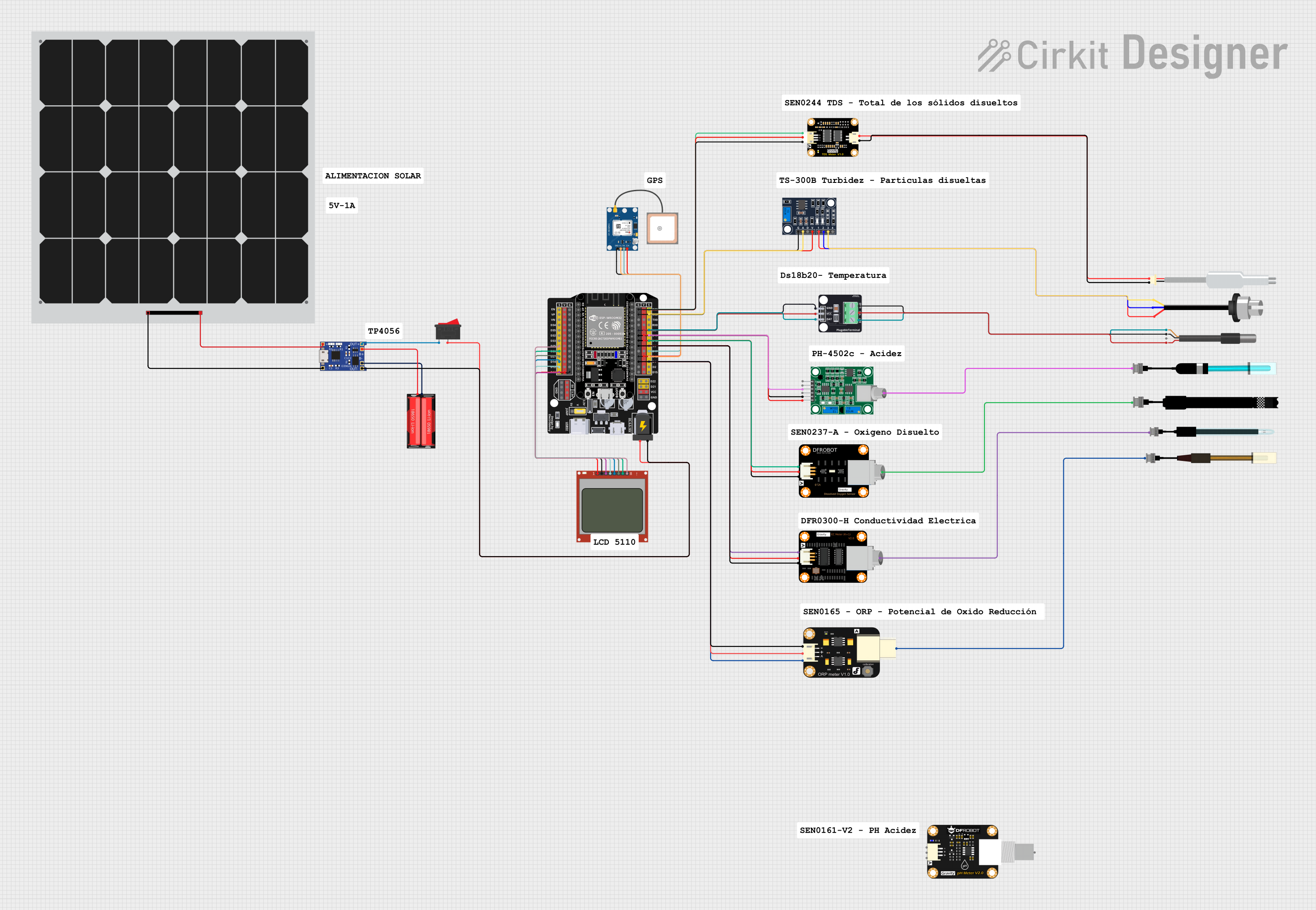
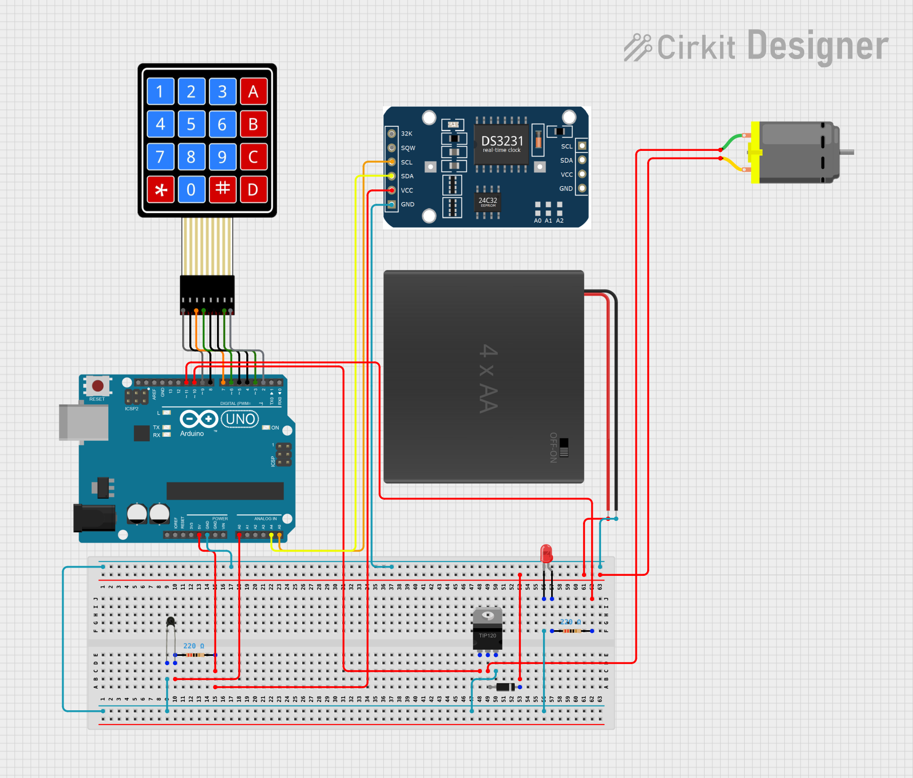
Explore Projects Built with xt60
Common Applications
- RC vehicles (cars, planes, drones, and boats)
- Lithium Polymer (LiPo) battery connections
- Electric bikes and scooters
- High-current power systems
- DIY electronics projects requiring secure power connections
Technical Specifications
Key Technical Details
| Parameter | Value |
|---|---|
| Maximum Current Rating | 60A (continuous) |
| Voltage Rating | Up to 500V DC |
| Contact Material | Gold-plated brass |
| Housing Material | Nylon (heat-resistant) |
| Connector Type | Male and Female (pair) |
| Wire Gauge Compatibility | 12 AWG to 10 AWG |
| Operating Temperature | -20°C to 120°C |
| Dimensions | 21.5mm x 16mm x 8mm (approx.) |
Pin Configuration and Descriptions
The XT60 connector consists of two pins: one for positive (+) and one for negative (-). The pins are polarized to prevent incorrect connections.
| Pin Name | Description |
|---|---|
| Positive (+) | Connects to the positive terminal of the power source or load |
| Negative (-) | Connects to the negative terminal of the power source or load |
Usage Instructions
How to Use the XT60 Connector in a Circuit
- Prepare the Wires: Strip the insulation from the ends of the wires you want to connect. Ensure the wire gauge is compatible (12 AWG to 10 AWG is recommended).
- Solder the Wires:
- Heat the soldering iron to the appropriate temperature (around 350°C to 400°C).
- Tin the exposed wire ends by applying a small amount of solder to them.
- Insert the tinned wire into the XT60 connector's solder cup and apply heat with the soldering iron. Add solder until the connection is secure.
- Check Polarity: Ensure the positive wire is connected to the positive pin and the negative wire to the negative pin. The XT60's polarized design helps prevent errors.
- Secure the Connection: Allow the solder to cool and solidify. Inspect the connection for any loose wires or cold solder joints.
- Insulate the Connection: Use heat shrink tubing or electrical tape to insulate the soldered area for added safety.
Important Considerations and Best Practices
- Avoid Overheating: Excessive heat during soldering can damage the nylon housing. Use a heat-resistant jig or clamp to hold the connector while soldering.
- Check for Shorts: After soldering, use a multimeter to verify there are no short circuits between the positive and negative pins.
- Use Proper Tools: A high-quality soldering iron, flux, and solder are essential for creating reliable connections.
- Match Connectors: Always use XT60 connectors in pairs (male and female) to ensure compatibility and a secure fit.
Example: Connecting an XT60 to an Arduino UNO Power Supply
While the XT60 is not directly compatible with the Arduino UNO, it can be used to connect a LiPo battery to a voltage regulator, which then powers the Arduino. Below is an example of how to use an XT60 connector in such a setup:
// Example: Reading battery voltage from a LiPo connected via XT60
// Ensure a voltage divider is used to step down the battery voltage
// to a safe level for the Arduino's analog input (0-5V).

const int batteryPin = A0; // Analog pin connected to the voltage divider
float voltageDividerRatio = 5.7; // Adjust based on your resistor values

void setup() {
  Serial.begin(9600); // Initialize serial communication
}

void loop() {
  int rawValue = analogRead(batteryPin); // Read the analog input
  float batteryVoltage = (rawValue / 1023.0) * 5.0 * voltageDividerRatio;

  // Print the battery voltage to the Serial Monitor
  Serial.print("Battery Voltage: ");
  Serial.print(batteryVoltage);
  Serial.println(" V");

  delay(1000); // Wait for 1 second before the next reading
}
Troubleshooting and FAQs
Common Issues and Solutions
Loose Connections:
- Issue: The wires are not securely attached to the XT60 connector.
- Solution: Re-solder the wires, ensuring proper tinning and a solid connection.
Overheating During Soldering:
- Issue: The nylon housing melts or deforms during soldering.
- Solution: Use a heat-resistant jig to hold the connector and minimize soldering time.
Reverse Polarity:
- Issue: The positive and negative wires are connected incorrectly.
- Solution: Double-check the polarity before soldering. The XT60's design helps prevent reverse connections.
High Resistance or Voltage Drop:
- Issue: Poor solder joints cause increased resistance.
- Solution: Inspect the solder joints and re-solder if necessary. Use high-quality solder and flux.
FAQs
Q: Can the XT60 handle more than 60A?
- A: The XT60 is rated for 60A continuous current. Exceeding this limit may cause overheating or damage. For higher currents, consider using XT90 connectors.
Q: Can I crimp wires instead of soldering them to the XT60?
- A: No, the XT60 is designed for soldered connections. Crimping is not recommended and may result in unreliable connections.
Q: Is the XT60 waterproof?
- A: No, the XT60 is not waterproof. If used in wet environments, additional waterproofing measures (e.g., heat shrink tubing with adhesive) are required.
Q: Can I use the XT60 with smaller wire gauges?
- A: While it is possible, smaller wires may not fit securely in the solder cups and could result in poor connections. Use wires within the recommended range (12 AWG to 10 AWG).
This concludes the XT60 documentation.