How to Use Arduino nano: Examples, Pinouts, and Specs
Introduction
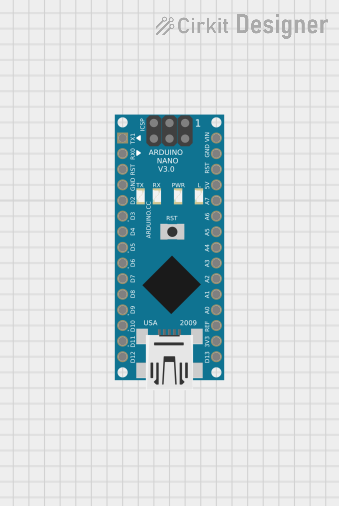
The Arduino Nano by Judah is a compact microcontroller board based on the ATmega328P microcontroller. Designed for easy integration into a wide range of projects, the Arduino Nano offers a small form factor without compromising on functionality. It features both digital and analog input/output pins, USB connectivity for programming and communication, and full compatibility with the Arduino IDE.
Explore Projects Built with Arduino nano


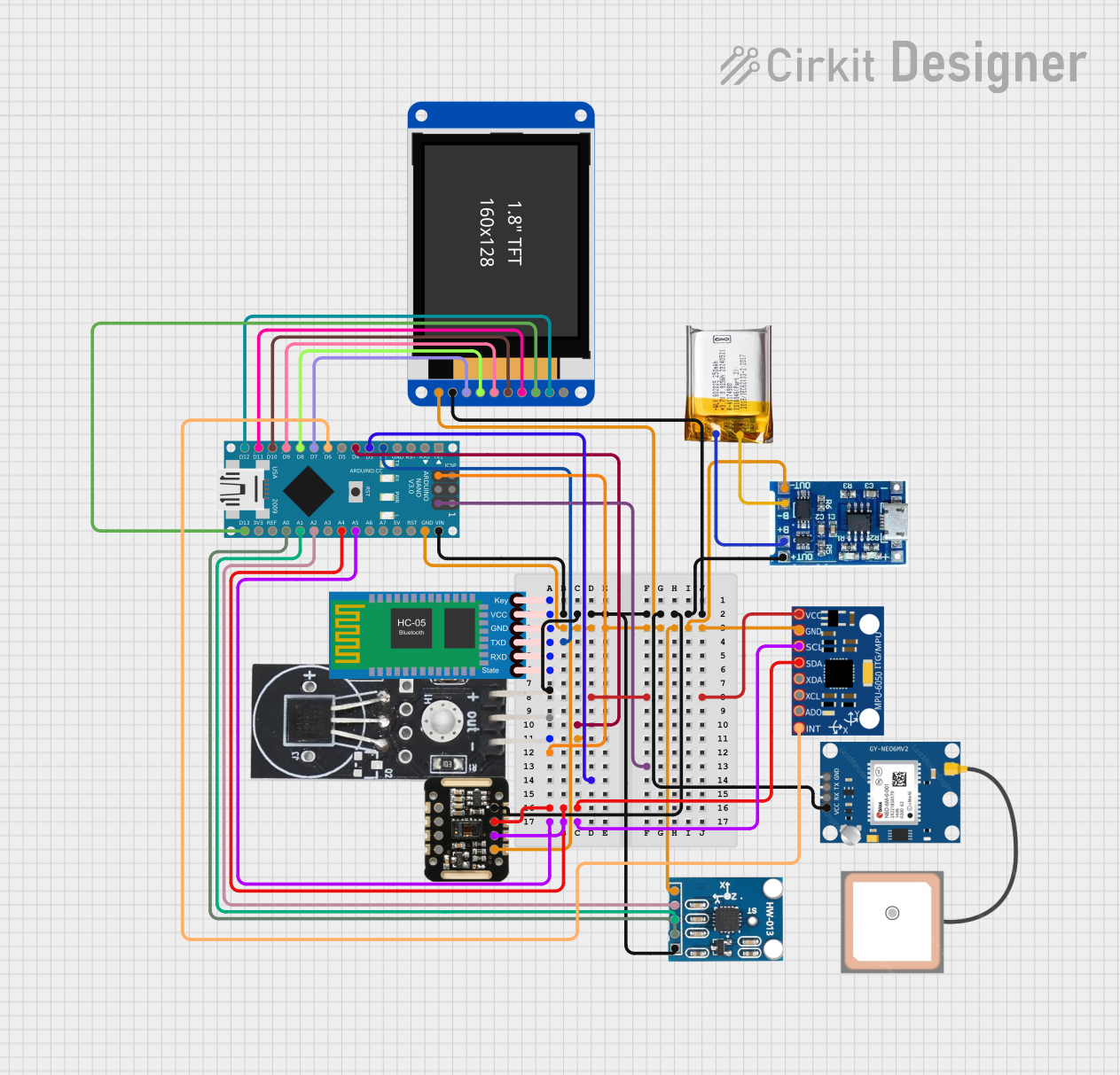
Explore Projects Built with Arduino nano
Common Applications and Use Cases
- Prototyping and development of embedded systems
- Robotics and automation projects
- IoT (Internet of Things) devices
- Sensor data acquisition and processing
- Wearable electronics
- Educational tools for learning microcontroller programming
Technical Specifications
The following table outlines the key technical details of the Arduino Nano:
| Specification | Details |
|---|---|
| Microcontroller | ATmega328P |
| Operating Voltage | 5V |
| Input Voltage (recommended) | 7-12V |
| Input Voltage (limit) | 6-20V |
| Digital I/O Pins | 14 (6 PWM outputs) |
| Analog Input Pins | 8 |
| DC Current per I/O Pin | 40 mA |
| Flash Memory | 32 KB (2 KB used by bootloader) |
| SRAM | 2 KB |
| EEPROM | 1 KB |
| Clock Speed | 16 MHz |
| USB Connectivity | Mini-B USB |
| Dimensions | 18 x 45 mm |
| Weight | 7 g |
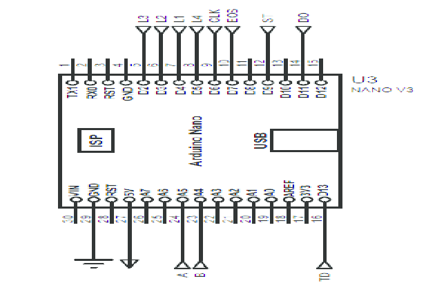
Pin Configuration and Descriptions
The Arduino Nano has a total of 30 pins. Below is a detailed description of the pin configuration:
| Pin | Type | Description |
|---|---|---|
| D0-D13 | Digital I/O | General-purpose digital input/output pins. D3, D5, D6, D9, D10, D11 support PWM. |
| A0-A7 | Analog Input | Analog input pins with a 10-bit resolution. Can also be used as digital pins. |
| VIN | Power Input | Input voltage to the board when using an external power source (7-12V). |
| 5V | Power Output | Regulated 5V output from the onboard voltage regulator. |
| 3.3V | Power Output | Regulated 3.3V output (maximum current: 50 mA). |
| GND | Ground | Ground pins. |
| RESET | Reset | Resets the microcontroller. |
| TX (D1) | UART Transmit | Transmit pin for serial communication. |
| RX (D0) | UART Receive | Receive pin for serial communication. |
| ICSP | Programming | In-Circuit Serial Programming header for flashing firmware. |
Usage Instructions
How to Use the Arduino Nano in a Circuit
Powering the Board:
- Connect the Arduino Nano to your computer via a Mini-B USB cable for programming and power.
- Alternatively, supply power through the VIN pin (7-12V recommended) or the 5V pin (regulated 5V).
Programming the Board:
- Install the Arduino IDE from the official Arduino website.
- Select "Arduino Nano" as the board type in the IDE.
- Choose the correct processor (ATmega328P) and port under the "Tools" menu.
- Write your code in the IDE and upload it to the board using the "Upload" button.
Connecting Components:
- Use the digital pins (D0-D13) for digital input/output operations.
- Use the analog pins (A0-A7) for reading analog signals or as additional digital pins.
- Connect sensors, actuators, and other peripherals as needed, ensuring current and voltage limits are not exceeded.
Important Considerations and Best Practices
- Avoid drawing more than 40 mA from any single I/O pin to prevent damage to the microcontroller.
- Use external pull-up or pull-down resistors for stable digital input signals.
- When using the board with high-current devices (e.g., motors), use external power supplies and appropriate driver circuits.
- Ensure proper grounding between the Arduino Nano and all connected components.
Example Code for Arduino Nano with an LED
The following example demonstrates how to blink an LED connected to pin D13:
// This example code blinks an LED connected to pin D13 on the Arduino Nano.
// The LED will turn on for 1 second and off for 1 second in a loop.

void setup() {
  pinMode(13, OUTPUT); // Set pin D13 as an output pin
}

void loop() {
  digitalWrite(13, HIGH); // Turn the LED on
  delay(1000);            // Wait for 1 second
  digitalWrite(13, LOW);  // Turn the LED off
  delay(1000);            // Wait for 1 second
}
Troubleshooting and FAQs
Common Issues and Solutions
The Arduino Nano is not recognized by the computer:
- Ensure the correct USB driver is installed for the board.
- Try using a different USB cable or port.
- Check if the board is powered (the onboard LED should light up).
Code upload fails with an error:
- Verify that the correct board type and processor are selected in the Arduino IDE.
- Ensure the correct COM port is selected under the "Tools" menu.
- Press the reset button on the board just before uploading the code.
The board resets unexpectedly:
- Check for power supply issues. Ensure the input voltage is within the recommended range.
- Avoid drawing excessive current from the I/O pins.
Analog readings are unstable:
- Use proper decoupling capacitors near the analog input pins.
- Ensure the sensor or input device is properly grounded.
FAQs
Q: Can I power the Arduino Nano with a battery?
A: Yes, you can power the Arduino Nano using a battery. Connect the battery's positive terminal to the VIN pin and the negative terminal to GND. Ensure the voltage is within the recommended range (7-12V).
Q: How do I reset the Arduino Nano?
A: You can reset the Arduino Nano by pressing the onboard reset button or by connecting the RESET pin to GND momentarily.
Q: Can I use the Arduino Nano for wireless communication?
A: Yes, you can use the Arduino Nano with external wireless modules such as Bluetooth (e.g., HC-05) or Wi-Fi (e.g., ESP8266) for wireless communication.
Q: What is the maximum current the Arduino Nano can supply?
A: The 5V pin can supply up to 500 mA when powered via USB, but this depends on the USB port's capacity. The 3.3V pin can supply up to 50 mA.
By following this documentation, you can effectively integrate the Arduino Nano into your projects and troubleshoot common issues with ease.