How to Use ttl to rs485: Examples, Pinouts, and Specs
Introduction
The TTL to RS485 converter is a versatile electronic component designed to bridge the gap between TTL (Transistor-Transistor Logic) devices and RS-485 serial communication systems. RS-485 is widely used for long-distance, high-speed, and noise-resistant data transmission in industrial and commercial applications. This converter enables TTL-based microcontrollers, such as Arduino or Raspberry Pi, to communicate seamlessly with RS-485 networks.
Explore Projects Built with ttl to rs485


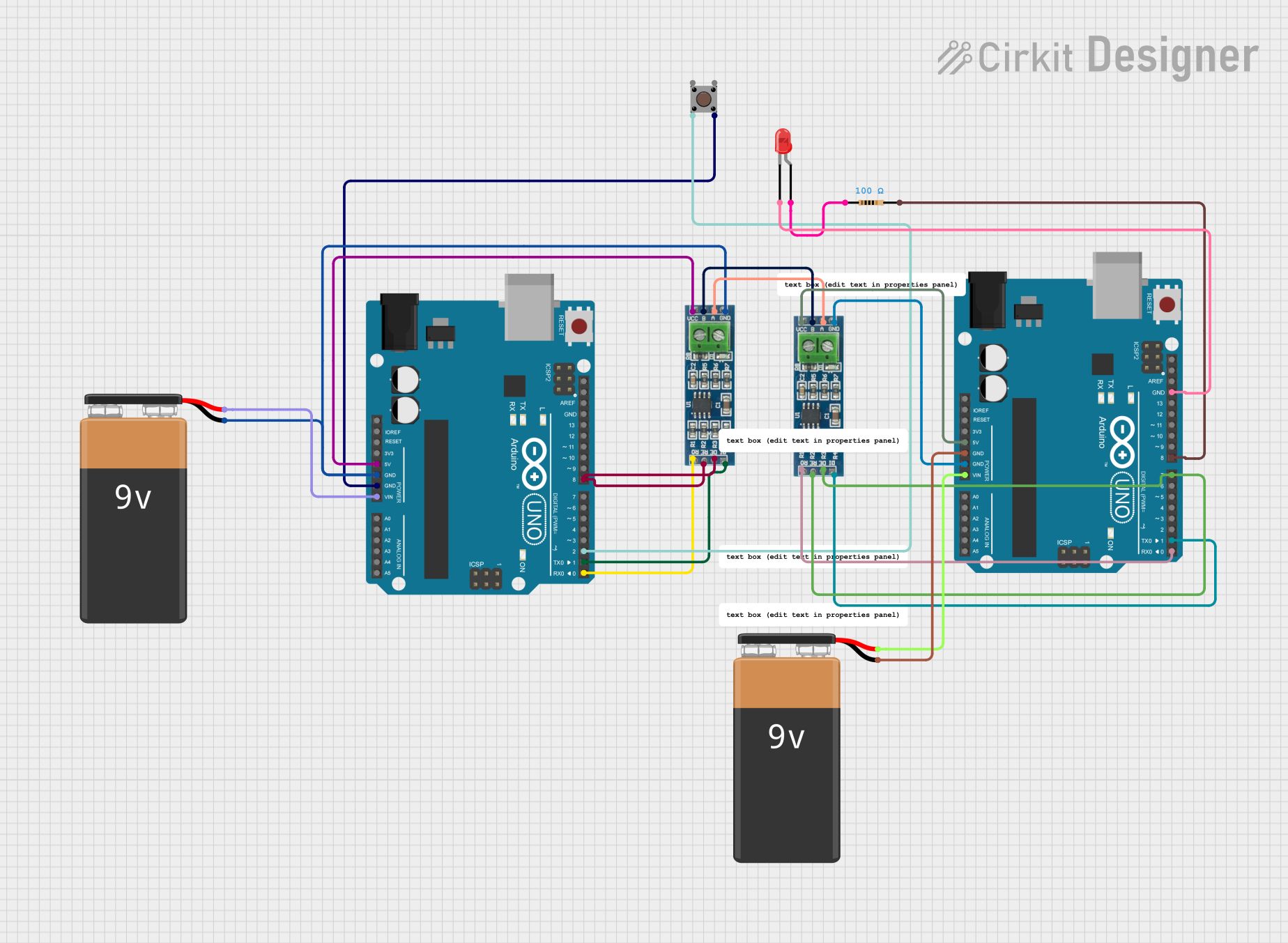
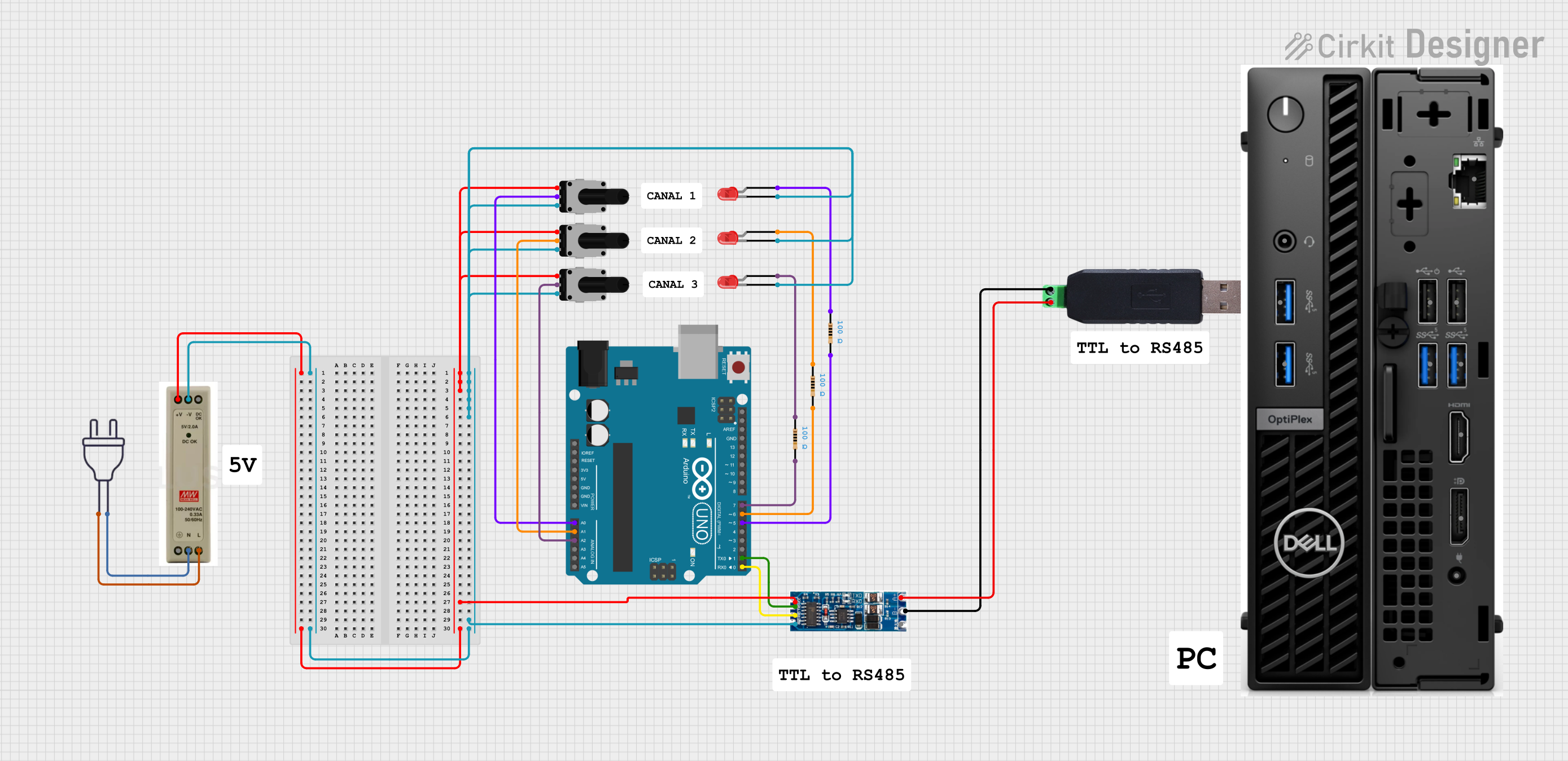
Explore Projects Built with ttl to rs485
Common Applications and Use Cases
- Industrial automation and control systems
- Long-distance serial communication (up to 1200 meters)
- Building management systems (e.g., HVAC, lighting control)
- Data acquisition systems
- RS-485-based protocols like Modbus
Technical Specifications
Key Technical Details
- Input Voltage (VCC): 3.3V to 5V
- Communication Standard: RS-485 (differential signaling)
- Data Rate: Up to 10 Mbps (depending on cable length)
- Transmission Distance: Up to 1200 meters (at lower baud rates)
- Operating Temperature: -40°C to 85°C
- Driver Enable (DE) and Receiver Enable (RE): Controlled via TTL logic
- ESD Protection: ±15kV (human body model)
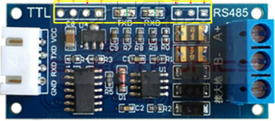
Pin Configuration and Descriptions
The TTL to RS485 converter typically has the following pin configuration:
| Pin Name | Type | Description |
|---|---|---|
| VCC | Power Input | Connect to 3.3V or 5V power supply. |
| GND | Ground | Connect to the ground of the power supply. |
| TXD | TTL Input | Transmit data from the TTL device (e.g., Arduino TX pin). |
| RXD | TTL Output | Receive data to the TTL device (e.g., Arduino RX pin). |
| DE | TTL Input | Driver Enable: Set HIGH to enable RS-485 transmission. |
| RE | TTL Input | Receiver Enable: Set LOW to enable RS-485 reception. |
| A | RS-485 Signal | Non-inverting RS-485 signal line (connect to RS-485 bus). |
| B | RS-485 Signal | Inverting RS-485 signal line (connect to RS-485 bus). |
Usage Instructions
How to Use the Component in a Circuit
Power the Converter:
- Connect the
VCCpin to a 3.3V or 5V power source. - Connect the
GNDpin to the ground of the power source.
- Connect the
Connect TTL Device:
- Connect the
TXDpin of the converter to the TX pin of the TTL device (e.g., Arduino). - Connect the
RXDpin of the converter to the RX pin of the TTL device.
- Connect the
Enable Transmission and Reception:
- Set the
DEpin HIGH to enable RS-485 transmission. - Set the
REpin LOW to enable RS-485 reception. - For automatic control, connect
DEandREtogether and control them with a single GPIO pin.
- Set the
Connect RS-485 Bus:
- Connect the
AandBpins to the RS-485 bus. Ensure proper termination resistors (typically 120Ω) are used at both ends of the RS-485 bus for reliable communication.
- Connect the
Write Code for Communication:
- Use a UART library or serial communication functions to send and receive data.
Important Considerations and Best Practices
- Termination Resistors: Always use 120Ω termination resistors at both ends of the RS-485 bus to prevent signal reflections.
- Biasing Resistors: Add pull-up and pull-down resistors on the
AandBlines to maintain a known idle state. - Cable Selection: Use twisted-pair cables for RS-485 communication to minimize noise and signal degradation.
- Grounding: Ensure a common ground between all devices on the RS-485 network.
- Baud Rate vs. Distance: Higher baud rates reduce the maximum transmission distance. Choose an appropriate baud rate for your application.
Example Code for Arduino UNO
// Example: Sending and receiving data using TTL to RS485 converter
// Connect DE and RE pins together to pin 2 on Arduino for control

#define DE_RE_PIN 2  // Pin to control DE and RE
#define TX_PIN 1     // Arduino TX pin
#define RX_PIN 0     // Arduino RX pin

void setup() {
  pinMode(DE_RE_PIN, OUTPUT);  // Set DE/RE pin as output
  digitalWrite(DE_RE_PIN, LOW); // Set to LOW for receiving initially

  Serial.begin(9600);  // Initialize serial communication at 9600 baud
}

void loop() {
  // Transmit data
  digitalWrite(DE_RE_PIN, HIGH); // Enable transmission
  Serial.println("Hello RS-485!"); // Send data
  delay(100); // Wait for data to be sent
  digitalWrite(DE_RE_PIN, LOW);  // Enable reception

  // Receive data
  if (Serial.available()) {
    String receivedData = Serial.readString(); // Read incoming data
    Serial.println("Received: " + receivedData); // Print received data
  }

  delay(1000); // Wait before next transmission
}
Troubleshooting and FAQs
Common Issues and Solutions
No Data Transmission:
- Ensure the
DEpin is set HIGH during transmission. - Verify the RS-485 bus connections (
AandBlines).
- Ensure the
No Data Reception:
- Ensure the
REpin is set LOW during reception. - Check if the TTL device's RX pin is correctly connected to the converter's
RXDpin.
- Ensure the
Data Corruption or Noise:
- Use proper termination resistors (120Ω) at both ends of the RS-485 bus.
- Use twisted-pair cables for the RS-485 lines.
Communication Fails Over Long Distances:
- Reduce the baud rate to increase the maximum transmission distance.
- Ensure proper grounding and shielding of cables.
FAQs
Q: Can I use this converter with a 3.3V microcontroller?
A: Yes, the converter supports both 3.3V and 5V logic levels. Ensure the VCC pin matches the microcontroller's voltage.
Q: How many devices can I connect to the RS-485 bus?
A: RS-485 supports up to 32 devices on a single bus. Use repeaters for larger networks.
Q: Do I need to manually control the DE and RE pins?
A: Yes, unless the converter has an automatic flow control feature. You can connect DE and RE together for simplified control.
Q: What is the maximum cable length for RS-485?
A: The maximum length is 1200 meters at lower baud rates (e.g., 9600 bps). For higher baud rates, the distance decreases.