How to Use Adafruit TPS61023: Examples, Pinouts, and Specs
Introduction
The Adafruit TPS61023 is a high-efficiency boost converter breakout board designed to step up low voltage inputs to higher voltage outputs. This component is particularly useful in battery-powered applications where the input voltage is lower than the required operating voltage of the device. It is commonly used in portable electronics, IoT devices, and small robotics to maintain a stable voltage supply.
Explore Projects Built with Adafruit TPS61023

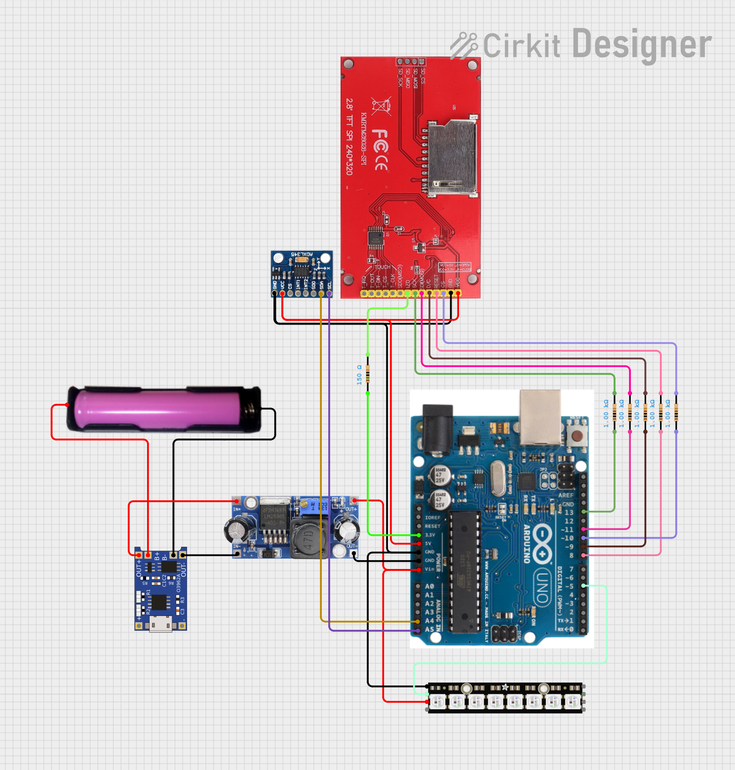
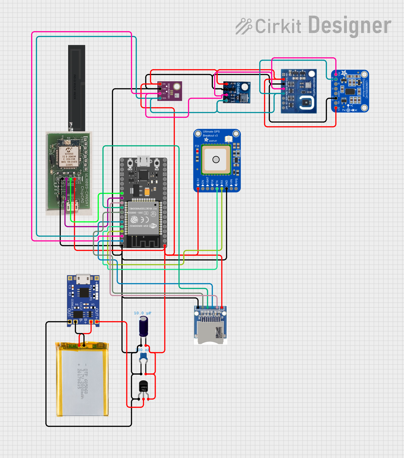

Explore Projects Built with Adafruit TPS61023
Common Applications and Use Cases
- Powering devices that require a higher voltage than the battery output
- Portable electronic projects with power supply requirements
- IoT devices with specific voltage needs
- Small robotics and embedded systems
Technical Specifications
The Adafruit TPS61023 boost converter has the following key technical specifications:
| Parameter | Specification |
|---|---|
| Input Voltage (VIN) | 1.8V to 5.5V |
| Output Voltage (VOUT) | Adjustable up to 15V |
| Maximum Output Current | 2A (with proper heat sinking) |
| Switching Frequency | 1.2MHz (typical) |
| Quiescent Current | 7µA (typical) |
| Efficiency | Up to 95% |
| Operating Temperature | -40°C to 85°C |
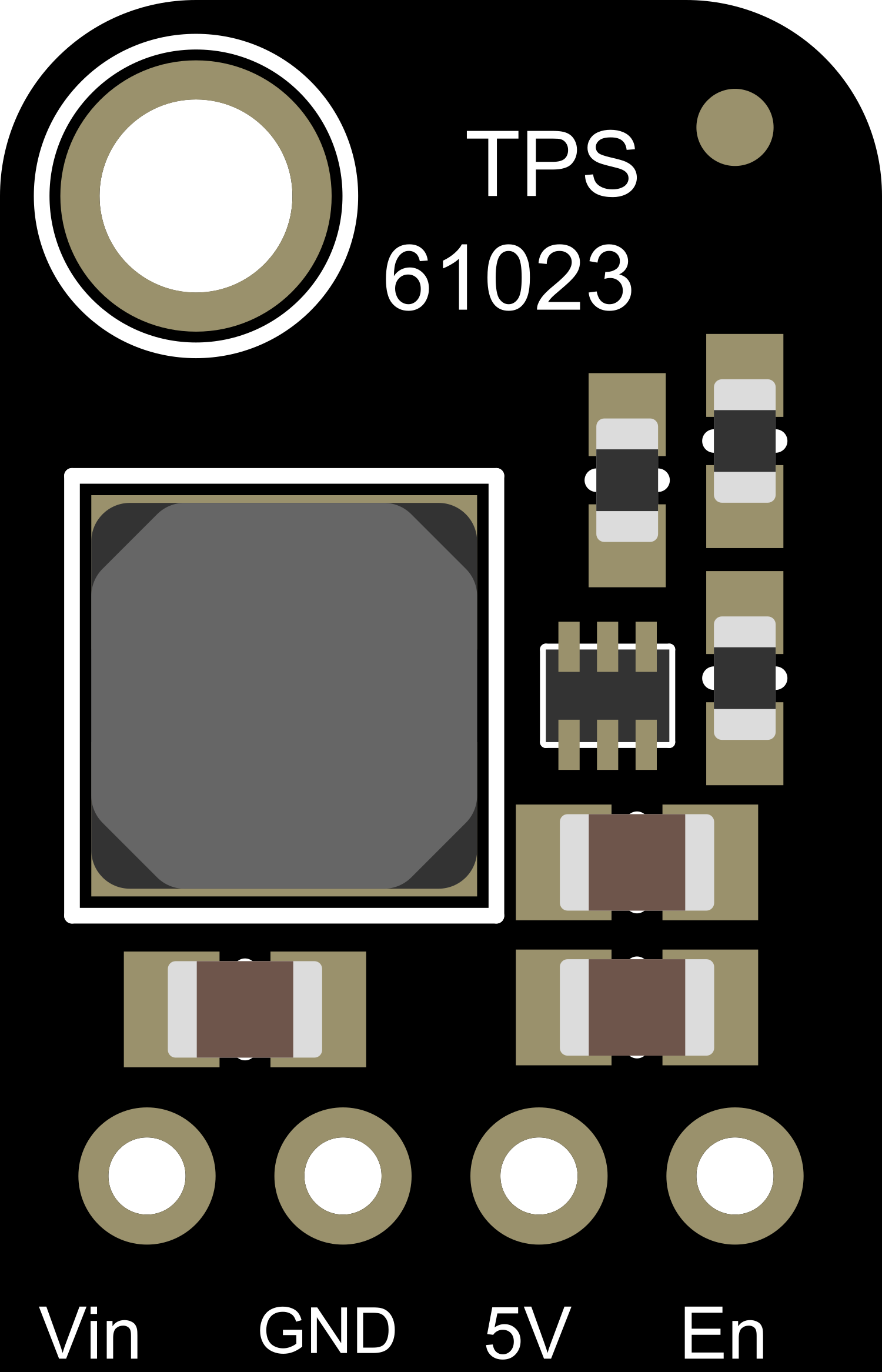
Pin Configuration and Descriptions
| Pin Name | Description |
|---|---|
| VIN | Input voltage to the boost converter. Connect to your low voltage supply. |
| GND | Ground reference for the circuit. Connect to the ground of your power supply. |
| VOUT | Output voltage from the boost converter. Connect to the device or circuit requiring higher voltage. |
| EN | Enable pin. Drive high to enable the boost converter, low to disable. |
| FB | Feedback pin. Connect to the output through a voltage divider to set the output voltage. |
Usage Instructions
How to Use the Component in a Circuit
- Connect the input voltage source to the VIN and GND pins.
- Set the desired output voltage by adjusting the voltage divider connected to the FB pin.
- Connect the EN pin to a logic high level to enable the boost converter.
- Connect the load to the VOUT and GND pins.
Important Considerations and Best Practices
- Ensure that the input voltage is within the specified range (1.8V to 5.5V).
- Do not exceed the maximum output current of 2A; provide adequate heat sinking if operating at high currents.
- Use a multimeter to verify the output voltage before connecting sensitive electronics.
- Place capacitors close to the VIN and VOUT pins to stabilize the input and output voltages.
- Avoid long wires to minimize voltage drop and noise in the circuit.
Troubleshooting and FAQs
Common Issues Users Might Face
- Output Voltage is Too Low or Unstable: Check the voltage divider on the FB pin and ensure that the capacitors are properly placed.
- Converter Does Not Power On: Verify that the EN pin is driven high and that the input voltage is within the specified range.
- Excessive Heat Generation: Ensure that the current draw is within limits and that adequate heat sinking is provided.
Solutions and Tips for Troubleshooting
- Double-check all connections and ensure that the solder joints are solid and not causing intermittent connections.
- Measure the input voltage to confirm that it is within the specified range for the TPS61023.
- If the output voltage is incorrect, adjust the voltage divider resistors connected to the FB pin.
Example Code for Arduino UNO
Below is an example code snippet for controlling the Adafruit TPS61023 with an Arduino UNO. This example assumes you have connected the EN pin to a digital pin on the Arduino (e.g., pin 7).
// Define the pin connected to the EN pin of the TPS61023
const int enablePin = 7;

void setup() {
  // Set the enable pin as an output
  pinMode(enablePin, OUTPUT);

  // Start the serial communication for debugging
  Serial.begin(9600);
}

void loop() {
  // Enable the boost converter
  digitalWrite(enablePin, HIGH);
  Serial.println("Boost converter enabled");
  delay(5000); // Keep enabled for 5 seconds

  // Disable the boost converter
  digitalWrite(enablePin, LOW);
  Serial.println("Boost converter disabled");
  delay(5000); // Keep disabled for 5 seconds
}
This code toggles the boost converter on and off every 5 seconds, which can be observed by measuring the voltage at the VOUT pin or by connecting an LED (with a current-limiting resistor) to the output.
Remember to keep code comments concise and within the 80 character line length limit. Adjust the delay times as needed for your specific application.