How to Use DY-HV20T: Examples, Pinouts, and Specs
Introduction
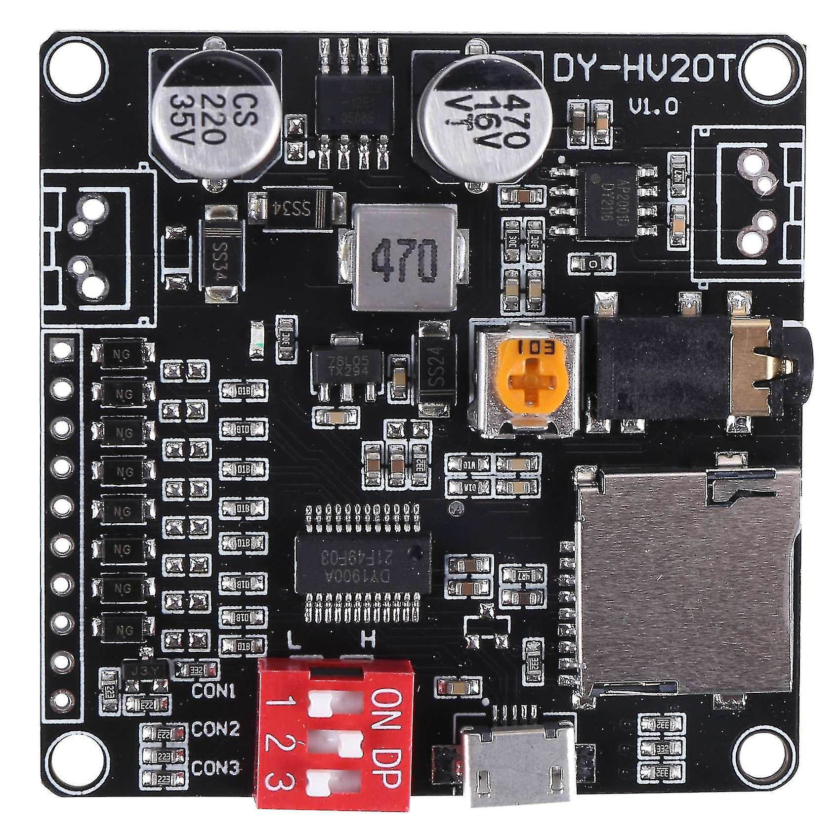
The DY-HV20T is a high-voltage relay designed for switching applications in various electronic circuits. It features a compact design, high insulation resistance, and the ability to handle high voltage loads. This makes it an ideal choice for power management and control systems. The DY-HV20T is widely used in industrial automation, home appliances, and energy management systems where reliable high-voltage switching is required.
Explore Projects Built with DY-HV20T

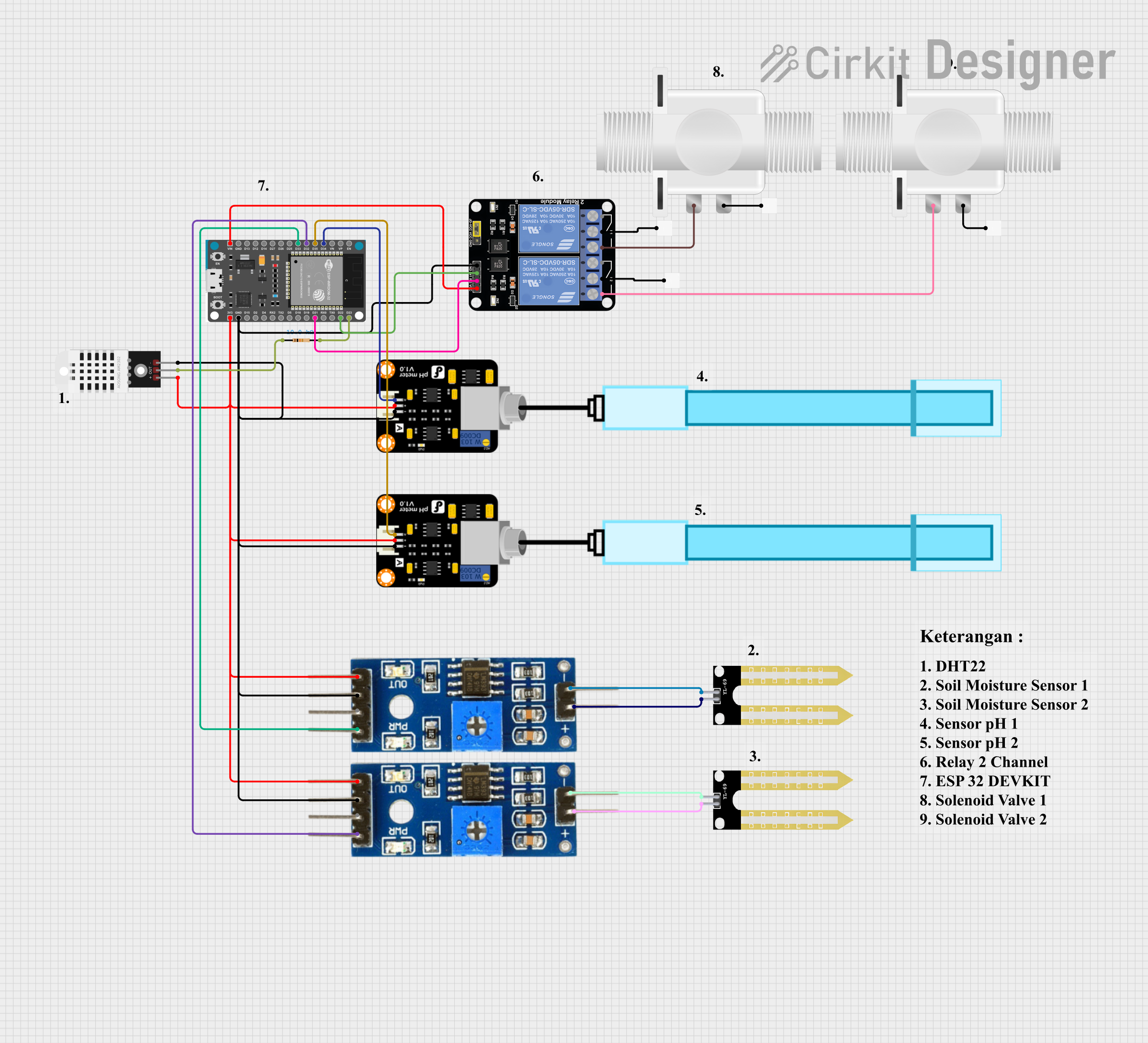

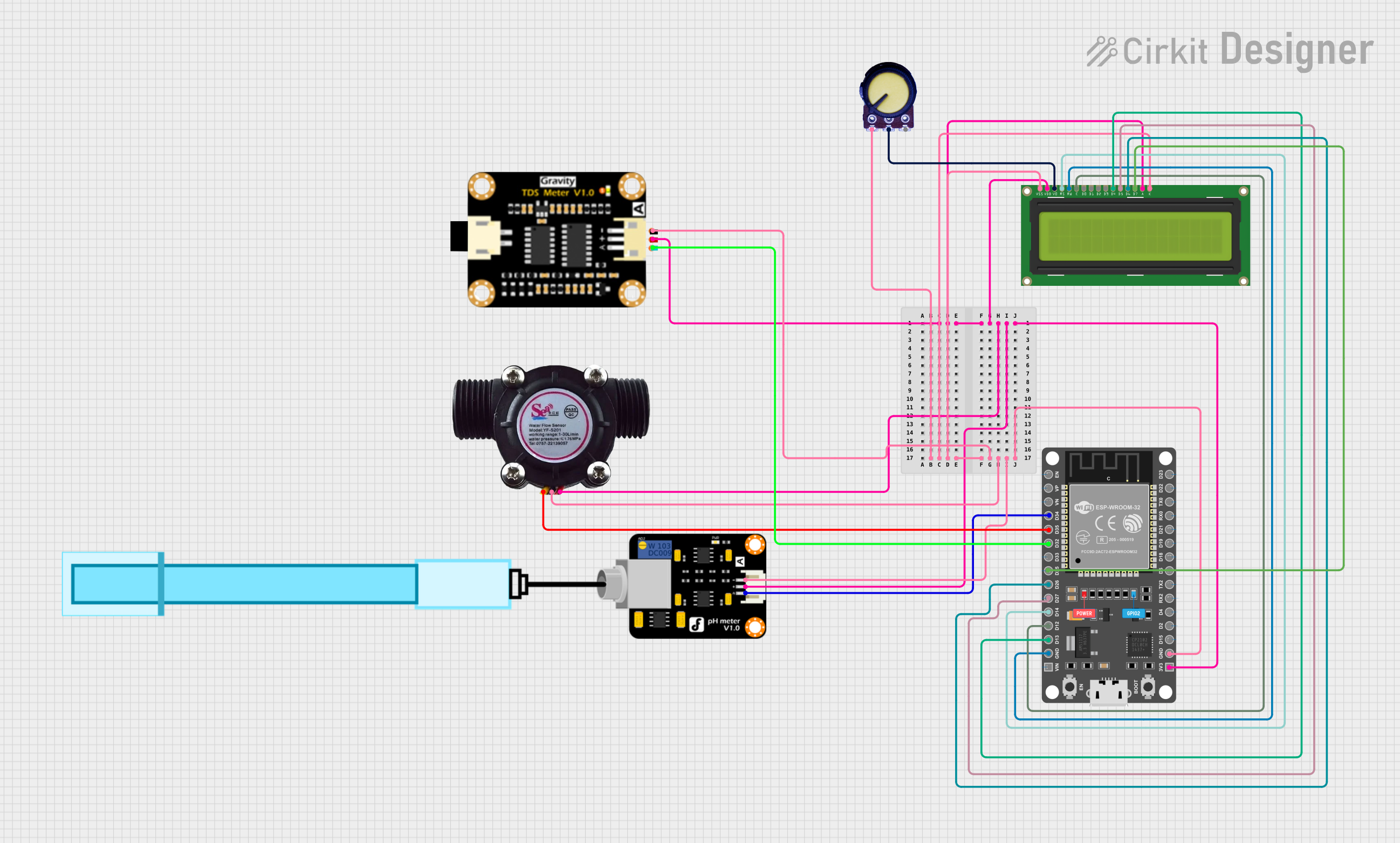
Explore Projects Built with DY-HV20T
Common Applications:
- Power management systems
- Industrial automation
- Home appliances
- Energy control and distribution systems
- High-voltage signal switching
Technical Specifications
Key Technical Details:
| Parameter | Value |
|---|---|
| Operating Voltage | 12V DC |
| Switching Voltage | Up to 20kV |
| Switching Current | Up to 1A |
| Insulation Resistance | ≥ 1000MΩ |
| Contact Resistance | ≤ 50mΩ |
| Operating Temperature | -40°C to +85°C |
| Dimensions | 30mm x 15mm x 10mm |
| Weight | 12g |
Pin Configuration and Descriptions:
| Pin Number | Pin Name | Description |
|---|---|---|
| 1 | Coil+ | Positive terminal of the relay coil (12V DC) |
| 2 | Coil- | Negative terminal of the relay coil (GND) |
| 3 | Common (COM) | Common terminal for the relay contacts |
| 4 | Normally Open (NO) | Open circuit when the relay is inactive; closes when activated |
| 5 | Normally Closed (NC) | Closed circuit when the relay is inactive; opens when activated |
Usage Instructions
How to Use the DY-HV20T in a Circuit:
- Power the Relay Coil: Connect the
Coil+pin to a 12V DC power source and theCoil-pin to ground. This energizes the relay coil and switches the contacts. - Connect the Load:
- For a normally open (NO) configuration, connect the load between the
COMandNOpins. The circuit will close when the relay is activated. - For a normally closed (NC) configuration, connect the load between the
COMandNCpins. The circuit will open when the relay is activated.
- For a normally open (NO) configuration, connect the load between the
- Control the Relay: Use a microcontroller, such as an Arduino, or a transistor circuit to control the relay coil.
Important Considerations:
- Ensure the relay is operated within its specified voltage and current ratings to avoid damage.
- Use a flyback diode across the relay coil to protect the driving circuit from voltage spikes.
- Maintain proper insulation and spacing when handling high-voltage connections to ensure safety.
- Avoid switching currents or voltages beyond the relay's rated capacity.
Example: Controlling the DY-HV20T with an Arduino UNO
Below is an example of how to control the DY-HV20T relay using an Arduino UNO:
// Define the pin connected to the relay's Coil+ terminal
const int relayPin = 7;

void setup() {
  // Set the relay pin as an output
  pinMode(relayPin, OUTPUT);
}

void loop() {
  // Activate the relay by setting the pin HIGH
  digitalWrite(relayPin, HIGH);
  delay(1000); // Keep the relay on for 1 second

  // Deactivate the relay by setting the pin LOW
  digitalWrite(relayPin, LOW);
  delay(1000); // Keep the relay off for 1 second
}
Note: Use a transistor or relay driver circuit to interface the Arduino with the relay, as the Arduino's GPIO pins cannot directly supply the required current for the relay coil.
Troubleshooting and FAQs
Common Issues and Solutions:
Relay Not Activating:
- Cause: Insufficient voltage or current to the relay coil.
- Solution: Verify that the power supply provides 12V DC and sufficient current for the relay.
Contacts Not Switching:
- Cause: Incorrect wiring of the load or relay pins.
- Solution: Double-check the connections to the
COM,NO, andNCpins.
Voltage Spikes Damaging the Circuit:
- Cause: Lack of a flyback diode across the relay coil.
- Solution: Install a diode (e.g., 1N4007) across the
Coil+andCoil-pins, with the cathode connected toCoil+.
Overheating or Damage:
- Cause: Exceeding the relay's voltage or current ratings.
- Solution: Ensure the load does not exceed the relay's maximum switching voltage (20kV) or current (1A).
FAQs:
Q: Can the DY-HV20T handle AC loads?
A: Yes, the relay can switch both AC and DC loads, provided the voltage and current ratings are not exceeded.Q: What is the purpose of the flyback diode?
A: The flyback diode protects the driving circuit from voltage spikes generated when the relay coil is de-energized.Q: Can I use the DY-HV20T with a 5V microcontroller?
A: Yes, but you will need a transistor or relay driver circuit to step up the control signal to 12V for the relay coil.Q: How do I ensure safety when using high voltages?
A: Use proper insulation, maintain adequate spacing between high-voltage connections, and avoid direct contact with live circuits.