How to Use T3 LoRa32 V1.6.1: Examples, Pinouts, and Specs
Introduction
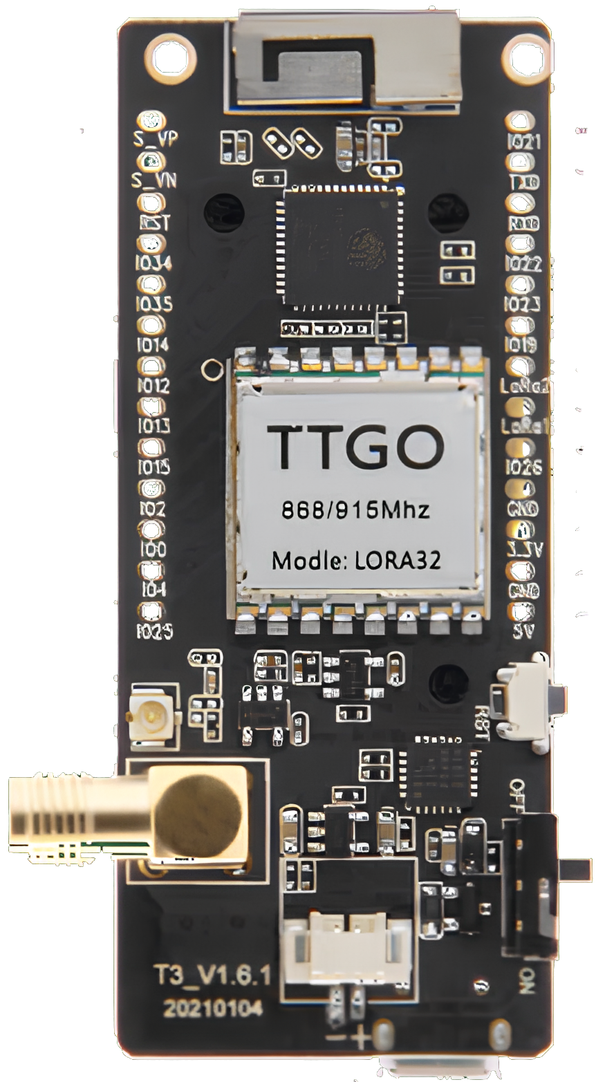
The T3 LoRa32 V1.6.1, manufactured by Lilygo, is a compact microcontroller board designed for low-power wireless communication in IoT applications. It features an ESP32 chip for processing, integrated Wi-Fi and Bluetooth capabilities, and a LoRa (Long Range) radio module for long-distance communication. This board is ideal for applications requiring remote data transmission, such as environmental monitoring, smart agriculture, and industrial IoT systems.
Explore Projects Built with T3 LoRa32 V1.6.1

Explore Projects Built with T3 LoRa32 V1.6.1
Common Applications and Use Cases
- Remote sensor networks for environmental data collection
- Smart agriculture systems (e.g., soil moisture monitoring)
- Industrial IoT for machine-to-machine communication
- Asset tracking and geolocation
- Home automation and smart city projects
Technical Specifications
Key Technical Details
| Parameter | Specification |
|---|---|
| Microcontroller | ESP32 (dual-core, 32-bit, Xtensa LX6 processor) |
| Clock Speed | Up to 240 MHz |
| Flash Memory | 4 MB (SPI Flash) |
| SRAM | 520 KB |
| Wireless Connectivity | Wi-Fi 802.11 b/g/n, Bluetooth 4.2 (BLE) |
| LoRa Frequency Bands | 433 MHz / 868 MHz / 915 MHz (region-dependent) |
| LoRa Modulation | Semtech SX1276 LoRa transceiver |
| Operating Voltage | 3.3V |
| Input Voltage Range | 5V (via USB) or 3.7V (via LiPo battery) |
| Power Consumption | Ultra-low power in deep sleep mode |
| GPIO Pins | 21 (including ADC, DAC, I2C, SPI, UART, PWM) |
| Display | Optional OLED (0.96-inch, 128x64 resolution) |
| Dimensions | 51 x 25.5 mm |
Pin Configuration and Descriptions
| Pin Name | Description |
|---|---|
| 3V3 | 3.3V power output |
| GND | Ground |
| VIN | Power input (5V via USB or 3.7V via LiPo battery) |
| GPIOxx | General-purpose input/output pins (varies by specific GPIO number) |
| ADCxx | Analog-to-digital converter pins |
| DACxx | Digital-to-analog converter pins |
| I2C SDA | I2C data line |
| I2C SCL | I2C clock line |
| SPI MOSI | SPI master-out, slave-in |
| SPI MISO | SPI master-in, slave-out |
| SPI SCK | SPI clock |
| UART TX | UART transmit line |
| UART RX | UART receive line |
| RST | Reset pin |
| LoRa Ant | LoRa antenna connection |
Usage Instructions
How to Use the T3 LoRa32 V1.6.1 in a Circuit
Powering the Board:
- Connect the board to a 5V USB power source or use a 3.7V LiPo battery via the JST connector.
- Ensure the power source provides sufficient current for both the ESP32 and LoRa module.
Connecting Peripherals:
- Use the GPIO pins for digital and analog input/output.
- Connect sensors, actuators, or displays as needed, ensuring proper voltage levels (3.3V logic).
Programming the Board:
- Install the ESP32 board package in the Arduino IDE or use the PlatformIO environment.
- Connect the board to your computer via USB and select the correct COM port and board type.
Using the LoRa Module:
- Attach the LoRa antenna to the designated connector.
- Use the
LoRalibrary in Arduino IDE to configure and send/receive data.
Important Considerations and Best Practices
- Antenna Connection: Always connect the LoRa antenna before powering the board to avoid damage to the LoRa module.
- Power Supply: Use a stable power source to ensure reliable operation, especially when using Wi-Fi, Bluetooth, or LoRa.
- Deep Sleep Mode: Utilize the ESP32's deep sleep mode to minimize power consumption in battery-powered applications.
- Frequency Compliance: Ensure the LoRa frequency band matches the regulations in your region (e.g., 868 MHz in Europe, 915 MHz in the US).
Example Code for Arduino IDE
The following example demonstrates how to send a simple message using the LoRa module:
#include <SPI.h>
#include <LoRa.h>

// Define LoRa parameters
#define LORA_SS 18    // LoRa chip select pin
#define LORA_RST 14   // LoRa reset pin
#define LORA_DIO0 26  // LoRa DIO0 pin

void setup() {
  // Initialize serial communication
  Serial.begin(9600);
  while (!Serial);

  // Initialize LoRa module
  Serial.println("Initializing LoRa...");
  LoRa.setPins(LORA_SS, LORA_RST, LORA_DIO0); // Set LoRa pins
  if (!LoRa.begin(915E6)) { // Set frequency to 915 MHz
    Serial.println("LoRa initialization failed!");
    while (1);
  }
  Serial.println("LoRa initialized successfully.");
}

void loop() {
  // Send a message
  Serial.println("Sending message...");
  LoRa.beginPacket();
  LoRa.print("Hello, LoRa!");
  LoRa.endPacket();

  // Wait for 5 seconds before sending the next message
  delay(5000);
}
Troubleshooting and FAQs
Common Issues and Solutions
LoRa Module Not Initializing:
- Ensure the LoRa antenna is connected properly.
- Verify the LoRa frequency matches your region's regulations.
- Check the wiring of the LoRa pins (SS, RST, DIO0).
Board Not Detected by Computer:
- Confirm the USB cable is functional and supports data transfer.
- Install the correct USB-to-serial driver for the ESP32.
Wi-Fi or Bluetooth Not Working:
- Ensure the ESP32 firmware is up to date.
- Check for interference from other devices operating on the same frequency.
High Power Consumption:
- Use deep sleep mode when the board is idle.
- Disconnect unused peripherals to reduce power draw.
FAQs
Q: Can I use the T3 LoRa32 V1.6.1 without an antenna?
A: No, operating the LoRa module without an antenna can damage the hardware.Q: What is the maximum range of the LoRa module?
A: The range depends on environmental factors but can reach up to 10 km in open areas.Q: Can I power the board with a 5V power bank?
A: Yes, the board can be powered via the USB port using a 5V power bank.Q: Is the board compatible with Arduino libraries?
A: Yes, the T3 LoRa32 V1.6.1 is compatible with most Arduino libraries for ESP32 and LoRa.