Cirkit Designer Logo
Cirkit Designer
Your all-in-one circuit design IDE
Home / 
Component Documentation

How to Use ESP 32U: Examples, Pinouts, and Specs

Image of ESP 32U
Cirkit Designer LogoDesign with ESP 32U in Cirkit Designer

Introduction

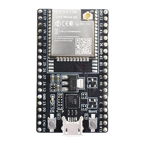
The ESP 32U is a low-power system on a chip (SoC) with integrated Wi-Fi and Bluetooth capabilities, designed specifically for Internet of Things (IoT) applications. It features a dual-core processor, a wide range of GPIO pins, and support for multiple communication protocols, making it a versatile choice for smart devices, wireless communication, and automation projects.

Explore Projects Built with ESP 32U

Use Cirkit Designer to design, explore, and prototype these projects online. Some projects support real-time simulation. Click "Open Project" to start designing instantly!
ESP32-Based Sensor Monitoring System with OLED Display and E-Stop
Image of MVP_design: A project utilizing ESP 32U in a practical application
This circuit features an ESP32 microcontroller that interfaces with a variety of sensors and output devices. It is powered by a Lipo battery through a buck converter, ensuring a stable voltage supply. The ESP32 collects data from a DHT11 temperature and humidity sensor and a vibration sensor, controls a buzzer, and displays information on an OLED screen. An emergency stop (E Stop) is connected for safety purposes, allowing the system to be quickly deactivated.
Cirkit Designer LogoOpen Project in Cirkit Designer
ESP32-Based Multi-Sensor Health Monitoring System with Bluetooth Connectivity
Image of circuit diagram: A project utilizing ESP 32U in a practical application
This circuit features an ESP32-WROOM-32UE microcontroller as the central processing unit, interfacing with a variety of sensors and modules. It includes a MAX30100 pulse oximeter and heart-rate sensor, an MLX90614 infrared thermometer, an HC-05 Bluetooth module for wireless communication, and a Neo 6M GPS module for location tracking. All components are powered by a common voltage supply and are connected to specific GPIO pins on the ESP32 for data exchange, with the sensors using I2C communication and the modules using UART.
Cirkit Designer LogoOpen Project in Cirkit Designer
ESP32-Based Smart Weather Station with Wi-Fi Connectivity
Image of flowchart 3D: A project utilizing ESP 32U in a practical application
This circuit features an ESP32 microcontroller interfacing with various sensors and modules, including a DHT22 temperature and humidity sensor, an ESP32 CAM for image capture, an I2C LCD screen for display, a load cell with an HX711 interface for weight measurement, and a buzzer for audio alerts. The ESP32 handles data acquisition, processing, and communication with these peripherals to create a multi-functional monitoring and alert system.
Cirkit Designer LogoOpen Project in Cirkit Designer
ESP32-Based Environmental Monitoring System with Ultrasonic, Gas, and IR Sensors
Image of Automatic Object Sensing Smart Dustbin: A project utilizing ESP 32U in a practical application
This circuit features an ESP32 microcontroller as the central processing unit, interfacing with a variety of sensors and output devices. It includes an HC-SR04 ultrasonic sensor for distance measurement, an IR sensor for object detection, an MQ-2 gas sensor for detecting combustible gases, and an OLED display for data visualization. Additionally, a Servomotor SG90 is connected for actuation purposes. The ESP32 reads sensor data and controls the servo based on programmed logic, which is not provided in the code input.
Cirkit Designer LogoOpen Project in Cirkit Designer

Explore Projects Built with ESP 32U

Use Cirkit Designer to design, explore, and prototype these projects online. Some projects support real-time simulation. Click "Open Project" to start designing instantly!
Image of MVP_design: A project utilizing ESP 32U in a practical application
ESP32-Based Sensor Monitoring System with OLED Display and E-Stop
This circuit features an ESP32 microcontroller that interfaces with a variety of sensors and output devices. It is powered by a Lipo battery through a buck converter, ensuring a stable voltage supply. The ESP32 collects data from a DHT11 temperature and humidity sensor and a vibration sensor, controls a buzzer, and displays information on an OLED screen. An emergency stop (E Stop) is connected for safety purposes, allowing the system to be quickly deactivated.
Cirkit Designer LogoOpen Project in Cirkit Designer
Image of circuit diagram: A project utilizing ESP 32U in a practical application
ESP32-Based Multi-Sensor Health Monitoring System with Bluetooth Connectivity
This circuit features an ESP32-WROOM-32UE microcontroller as the central processing unit, interfacing with a variety of sensors and modules. It includes a MAX30100 pulse oximeter and heart-rate sensor, an MLX90614 infrared thermometer, an HC-05 Bluetooth module for wireless communication, and a Neo 6M GPS module for location tracking. All components are powered by a common voltage supply and are connected to specific GPIO pins on the ESP32 for data exchange, with the sensors using I2C communication and the modules using UART.
Cirkit Designer LogoOpen Project in Cirkit Designer
Image of flowchart 3D: A project utilizing ESP 32U in a practical application
ESP32-Based Smart Weather Station with Wi-Fi Connectivity
This circuit features an ESP32 microcontroller interfacing with various sensors and modules, including a DHT22 temperature and humidity sensor, an ESP32 CAM for image capture, an I2C LCD screen for display, a load cell with an HX711 interface for weight measurement, and a buzzer for audio alerts. The ESP32 handles data acquisition, processing, and communication with these peripherals to create a multi-functional monitoring and alert system.
Cirkit Designer LogoOpen Project in Cirkit Designer
Image of Automatic Object Sensing Smart Dustbin: A project utilizing ESP 32U in a practical application
ESP32-Based Environmental Monitoring System with Ultrasonic, Gas, and IR Sensors
This circuit features an ESP32 microcontroller as the central processing unit, interfacing with a variety of sensors and output devices. It includes an HC-SR04 ultrasonic sensor for distance measurement, an IR sensor for object detection, an MQ-2 gas sensor for detecting combustible gases, and an OLED display for data visualization. Additionally, a Servomotor SG90 is connected for actuation purposes. The ESP32 reads sensor data and controls the servo based on programmed logic, which is not provided in the code input.
Cirkit Designer LogoOpen Project in Cirkit Designer

Common Applications

  • Smart home devices (e.g., smart lights, thermostats)
  • Wireless sensor networks
  • Wearable technology
  • Industrial IoT systems
  • Robotics and automation
  • Real-time data monitoring and logging

Technical Specifications

Key Technical Details

Specification Value
Processor Dual-core Xtensa® 32-bit LX6 CPU
Clock Speed Up to 240 MHz
Flash Memory 4 MB (external SPI flash)
SRAM 520 KB
Wi-Fi Standard 802.11 b/g/n
Bluetooth Version Bluetooth 4.2 (Classic and BLE)
Operating Voltage 3.0V - 3.6V
GPIO Pins 34 (multipurpose, configurable)
Communication Protocols UART, SPI, I2C, I2S, CAN, PWM
ADC Channels 18 (12-bit resolution)
DAC Channels 2
Power Consumption Ultra-low power (deep sleep: ~10 µA)
Operating Temperature -40°C to 85°C

Pin Configuration and Descriptions

The ESP 32U has 38 pins in total, with 34 GPIO pins that can be configured for various functions. Below is a summary of the key pins:

Pin Number Pin Name Functionality
1 EN Chip enable (active high)
2 IO0 GPIO0, boot mode selection
3 IO1 GPIO1, UART TX
4 IO2 GPIO2, ADC, PWM
5 IO3 GPIO3, UART RX
6-11 IO4-IO9 GPIO, ADC, PWM, I2C, SPI
12 IO10 GPIO10, ADC, PWM
13 IO11 GPIO11, UART, SPI
14-37 IO12-IO35 GPIO, ADC, DAC, I2C, SPI, PWM
38 GND Ground

Note: Some GPIO pins have specific restrictions or are used during boot. Refer to the ESP32 datasheet for detailed pin behavior.

Usage Instructions

How to Use the ESP 32U in a Circuit

  1. Power Supply: Provide a stable 3.3V power supply to the VCC pin. Ensure the current rating of the power source is sufficient for the ESP 32U's operation (minimum 500 mA recommended).
  2. Boot Mode: Connect GPIO0 to GND during boot to enter programming mode. For normal operation, leave GPIO0 unconnected or pull it high.
  3. Communication: Use UART pins (TX and RX) for serial communication with a microcontroller or computer. Alternatively, use SPI or I2C for interfacing with peripherals.
  4. Antenna: Ensure the onboard antenna has sufficient clearance from metallic objects to avoid signal interference.

Important Considerations

  • Voltage Levels: The ESP 32U operates at 3.3V logic levels. Avoid connecting 5V signals directly to its pins without a level shifter.
  • Deep Sleep Mode: Use deep sleep mode to minimize power consumption in battery-powered applications.
  • GPIO Restrictions: Some GPIO pins are used during boot and should not be pulled high or low during startup. Refer to the datasheet for details.

Example: Connecting ESP 32U to Arduino UNO

Below is an example of using the ESP 32U with an Arduino UNO to send data over Wi-Fi:

Circuit Connections

ESP 32U Pin Arduino UNO Pin
RX TX
TX RX
GND GND
VCC 3.3V

Arduino Code

#include <WiFi.h> // Include the Wi-Fi library for ESP32

const char* ssid = "Your_SSID";       // Replace with your Wi-Fi SSID
const char* password = "Your_Password"; // Replace with your Wi-Fi password

void setup() {
  Serial.begin(115200); // Initialize serial communication
  WiFi.begin(ssid, password); // Connect to Wi-Fi

  // Wait for connection
  while (WiFi.status() != WL_CONNECTED) {
    delay(1000);
    Serial.println("Connecting to Wi-Fi...");
  }

  Serial.println("Connected to Wi-Fi!");
  Serial.print("IP Address: ");
  Serial.println(WiFi.localIP()); // Print the device's IP address
}

void loop() {
  // Add your main code here
}

Note: Ensure the ESP 32U is in programming mode when uploading code. Disconnect GPIO0 from GND after uploading.

Troubleshooting and FAQs

Common Issues

  1. ESP 32U Not Connecting to Wi-Fi
    • Solution: Double-check the SSID and password. Ensure the router is within range and supports 2.4 GHz Wi-Fi (ESP32 does not support 5 GHz).
  2. Serial Communication Fails
    • Solution: Verify the RX and TX connections. Ensure the baud rate in the code matches the serial monitor.
  3. Device Not Detected During Programming
    • Solution: Ensure GPIO0 is connected to GND during boot. Check the USB-to-serial adapter and drivers.
  4. Random Resets or Instability
    • Solution: Use a stable power supply with sufficient current. Avoid using GPIO pins reserved for boot functions.

FAQs

  • Q: Can the ESP 32U operate on 5V?
    A: No, the ESP 32U operates at 3.3V. Use a voltage regulator or level shifter for 5V systems.

  • Q: How do I update the firmware?
    A: Use the ESP-IDF or Arduino IDE to upload new firmware via the UART interface.

  • Q: Can I use the ESP 32U for Bluetooth communication?
    A: Yes, the ESP 32U supports both Bluetooth Classic and BLE for wireless communication.

  • Q: What is the maximum range of the Wi-Fi module?
    A: The range depends on environmental factors but typically extends up to 100 meters in open spaces.

By following this documentation, you can effectively integrate the ESP 32U into your IoT projects and troubleshoot common issues.