
How to Use Mosfet: Examples, Pinouts, and Specs
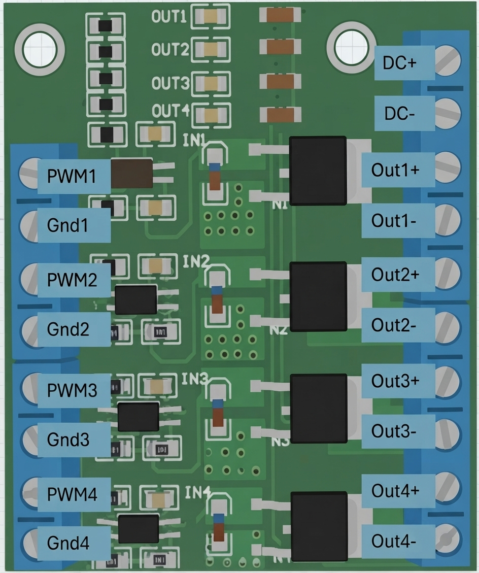
 Design with Mosfet in Cirkit Designer
Introduction
A Metal-Oxide-Semiconductor Field-Effect Transistor (MOSFET) is a type of transistor used for switching and amplifying electronic signals. It is widely used in power electronics and digital circuits due to its high efficiency and fast switching capabilities. MOSFETs are essential components in modern electronics, enabling the design of compact, energy-efficient devices.
Explore Projects Built with Mosfet
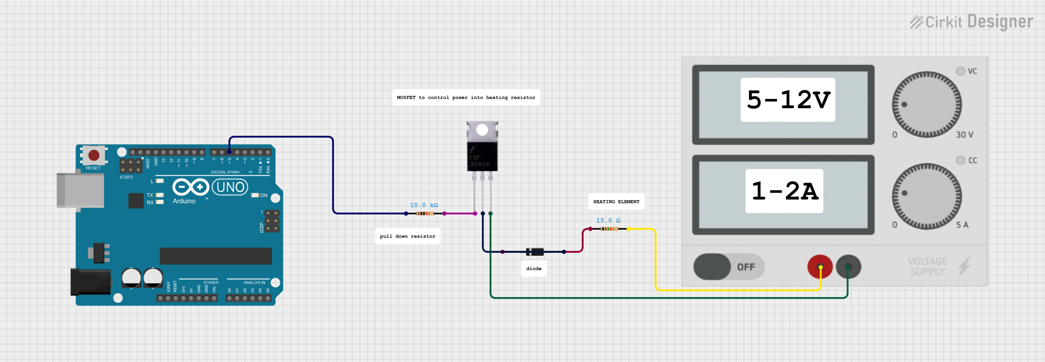 Open Project in Cirkit Designer
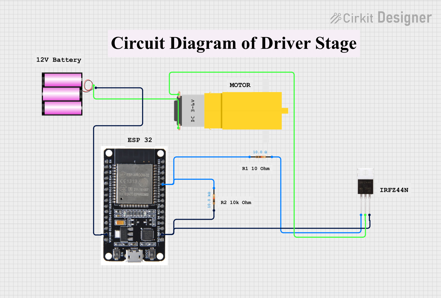 Open Project in Cirkit Designer
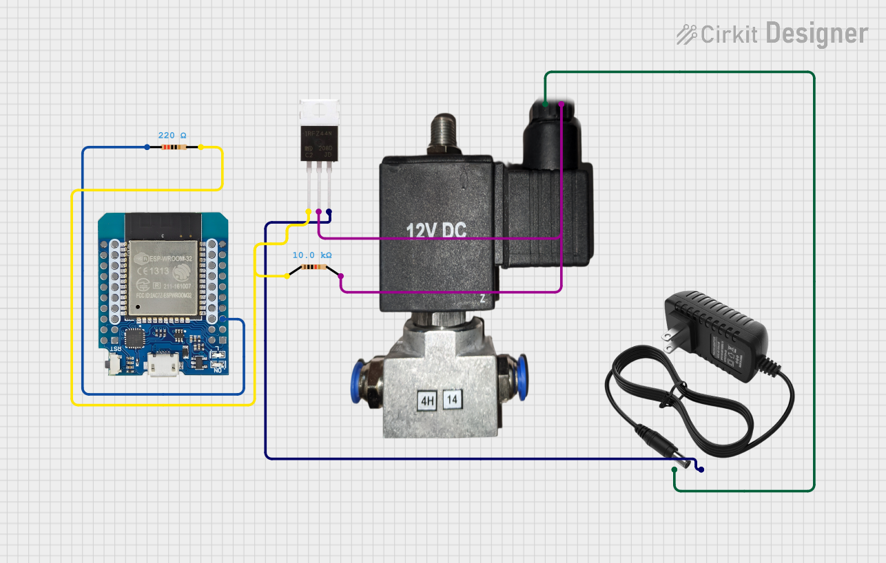 Open Project in Cirkit Designer
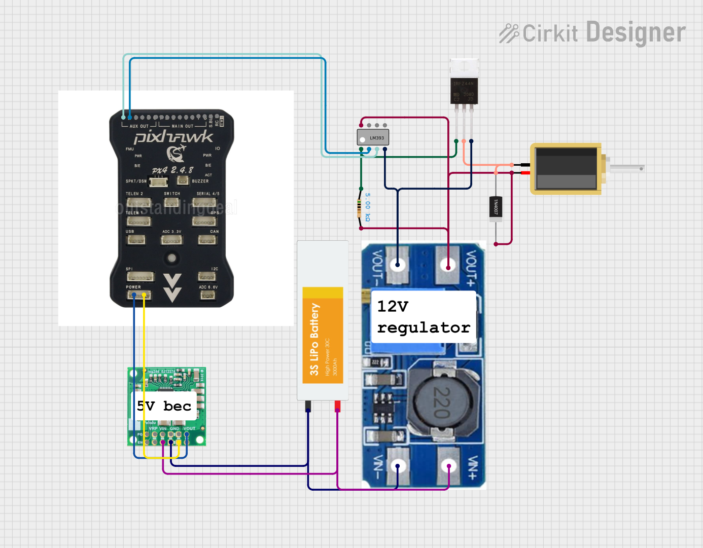 Open Project in Cirkit Designer
Explore Projects Built with Mosfet
Open Project in Cirkit DesignerOpen Project in Cirkit DesignerOpen Project in Cirkit DesignerOpen Project in Cirkit DesignerCommon Applications and Use Cases
- Power supplies and voltage regulators
- Motor control circuits
- Audio amplifiers
- Switching circuits in microcontrollers
- DC-DC converters
- LED drivers
Technical Specifications
MOSFETs come in various types and configurations. Below are the general technical specifications for a typical N-channel MOSFET (e.g., IRF540N):
Key Technical Details
- Type: N-channel or P-channel
- Voltage Rating (VDS): Up to 100V (varies by model)
- Current Rating (ID): Up to 33A (varies by model)
- Gate Threshold Voltage (VGS(th)): 2V to 4V
- RDS(on) (On-Resistance): 0.044Ω (typical for IRF540N)
- Power Dissipation: Up to 150W
- Switching Speed: Nanoseconds range
- Package Types: TO-220, TO-247, SMD packages
Pin Configuration and Descriptions
The MOSFET typically has three pins: Gate (G), Drain (D), and Source (S). Below is the pin configuration for a standard TO-220 package:
| Pin Number | Name | Description |
|---|---|---|
| 1 | Gate | Controls the flow of current between Drain and Source. |
| 2 | Drain | The terminal where current flows out of the MOSFET. |
| 3 | Source | The terminal where current flows into the MOSFET. |
Usage Instructions
How to Use the MOSFET in a Circuit
- Determine the Type: Identify whether you need an N-channel or P-channel MOSFET based on your circuit requirements.
- Connect the Gate: Use a resistor (typically 10Ω to 1kΩ) between the microcontroller or driver circuit and the Gate to limit inrush current.
- Connect the Drain: Attach the load (e.g., motor, LED) to the Drain terminal.
- Connect the Source: Connect the Source terminal to ground (N-channel) or the positive supply (P-channel).
- Gate Voltage: Ensure the Gate voltage (VGS) is sufficient to fully turn on the MOSFET (above the threshold voltage).
Important Considerations and Best Practices
- Heat Dissipation: Use a heatsink or cooling mechanism for high-power applications.
- Gate Drive Voltage: Ensure the Gate voltage is within the specified range to avoid damage.
- Flyback Diode: For inductive loads (e.g., motors), use a flyback diode across the load to protect the MOSFET from voltage spikes.
- Static Sensitivity: Handle the MOSFET carefully to avoid damage from electrostatic discharge (ESD).
Example: Using an N-Channel MOSFET with Arduino UNO
Below is an example of controlling an LED using an N-channel MOSFET and an Arduino UNO:
Circuit Connections
- Gate: Connect to Arduino digital pin (e.g., pin 9) through a 220Ω resistor.
- Drain: Connect to the negative terminal of the LED.
- Source: Connect to ground.
- LED Positive Terminal: Connect to a 12V power supply through a current-limiting resistor.
Arduino Code
// MOSFET Control Example
// This code turns an LED on and off using an N-channel MOSFET.
// Connect the MOSFET Gate to pin 9 of the Arduino.

const int mosfetPin = 9; // Pin connected to the MOSFET Gate

void setup() {
  pinMode(mosfetPin, OUTPUT); // Set the MOSFET pin as an output
}

void loop() {
  digitalWrite(mosfetPin, HIGH); // Turn the LED on
  delay(1000);                   // Wait for 1 second
  digitalWrite(mosfetPin, LOW);  // Turn the LED off
  delay(1000);                   // Wait for 1 second
}
Troubleshooting and FAQs
Common Issues
MOSFET Not Switching Properly:
- Ensure the Gate voltage is above the threshold voltage (VGS(th)).
- Check for proper connections and verify the resistor value at the Gate.
Overheating:
- Verify that the MOSFET is operating within its current and voltage ratings.
- Use a heatsink or cooling fan for high-power applications.
Load Not Turning On:
- Check the polarity of the MOSFET and ensure the Source and Drain are correctly connected.
- Verify the load and power supply connections.
FAQs
Q: Can I use a MOSFET without a resistor at the Gate?
A: It is not recommended. A resistor limits the inrush current to the Gate, protecting both the MOSFET and the driving circuit.
Q: How do I choose between an N-channel and P-channel MOSFET?
A: Use an N-channel MOSFET for low-side switching (Source connected to ground) and a P-channel MOSFET for high-side switching (Source connected to the positive supply).
Q: Can I drive a MOSFET directly with a microcontroller?
A: Yes, but ensure the microcontroller's output voltage is sufficient to fully turn on the MOSFET. Logic-level MOSFETs are ideal for this purpose.