Cirkit Designer Logo
Cirkit Designer
Your all-in-one circuit design IDE
Home / 
Component Documentation

How to Use ESP32 Wroom: Examples, Pinouts, and Specs

Image of ESP32 Wroom
Cirkit Designer LogoDesign with ESP32 Wroom in Cirkit Designer

Introduction

The ESP32 Wroom module is a powerful, versatile microcontroller unit equipped with WiFi and Bluetooth capabilities. Based on the ESP32 chip, it offers a dual-core processor that allows for multitasking and handling complex tasks. With a rich set of GPIO pins, analog inputs, and various communication interfaces, the ESP32 Wroom is an ideal choice for Internet of Things (IoT) projects, smart home applications, and any wireless-enabled device.

Explore Projects Built with ESP32 Wroom

Use Cirkit Designer to design, explore, and prototype these projects online. Some projects support real-time simulation. Click "Open Project" to start designing instantly!
ESP32-Based GPS Tracker with SD Card Logging and Barometric Sensor
Image of gps projekt circuit: A project utilizing ESP32 Wroom in a practical application
This circuit features an ESP32 Wroom Dev Kit as the main microcontroller, interfaced with an MPL3115A2 sensor for pressure and temperature readings, and a Neo 6M GPS module for location tracking. The ESP32 is also connected to an SD card reader for data logging purposes. A voltage regulator is used to step down the USB power supply to 3.3V, which powers the ESP32, the sensor, and the SD card reader.
Cirkit Designer LogoOpen Project in Cirkit Designer
ESP32-Based Vibration Motor Controller with I2C IO Expansion
Image of VIBRATYION: A project utilizing ESP32 Wroom in a practical application
This circuit features an ESP32 Wroom Dev Kit microcontroller interfaced with an MCP23017 I/O expansion board via I2C communication, utilizing GPIO 21 and GPIO 22 for SDA and SCL lines, respectively. A vibration motor is controlled by an NPN transistor acting as a switch, with a diode for back EMF protection and a resistor to limit base current. The ESP32 can control the motor by sending signals to the MCP23017, which then interfaces with the transistor to turn the motor on or off.
Cirkit Designer LogoOpen Project in Cirkit Designer
ESP32-Based Infrared Proximity Sensing System
Image of ir sensor: A project utilizing ESP32 Wroom in a practical application
This circuit features an ESP32 Wroom microcontroller connected to an Infrared Proximity Sensor. The ESP32's GPIO33 is interfaced with the sensor's output, allowing the microcontroller to read proximity data. The sensor is powered by the ESP32's 5V output, and both devices share a common ground.
Cirkit Designer LogoOpen Project in Cirkit Designer
ESP32 and Micro SD Card Module Data Logger
Image of MandIFInalWiring: A project utilizing ESP32 Wroom in a practical application
This circuit connects an ESP32 Wroom microcontroller to a Micro SD Card Module, enabling the ESP32 to read from and write to the SD card. The connections include SPI communication lines (CS, SCK, MOSI, MISO) and power lines (VCC, GND).
Cirkit Designer LogoOpen Project in Cirkit Designer

Explore Projects Built with ESP32 Wroom

Use Cirkit Designer to design, explore, and prototype these projects online. Some projects support real-time simulation. Click "Open Project" to start designing instantly!
Image of gps projekt circuit: A project utilizing ESP32 Wroom in a practical application
ESP32-Based GPS Tracker with SD Card Logging and Barometric Sensor
This circuit features an ESP32 Wroom Dev Kit as the main microcontroller, interfaced with an MPL3115A2 sensor for pressure and temperature readings, and a Neo 6M GPS module for location tracking. The ESP32 is also connected to an SD card reader for data logging purposes. A voltage regulator is used to step down the USB power supply to 3.3V, which powers the ESP32, the sensor, and the SD card reader.
Cirkit Designer LogoOpen Project in Cirkit Designer
Image of VIBRATYION: A project utilizing ESP32 Wroom in a practical application
ESP32-Based Vibration Motor Controller with I2C IO Expansion
This circuit features an ESP32 Wroom Dev Kit microcontroller interfaced with an MCP23017 I/O expansion board via I2C communication, utilizing GPIO 21 and GPIO 22 for SDA and SCL lines, respectively. A vibration motor is controlled by an NPN transistor acting as a switch, with a diode for back EMF protection and a resistor to limit base current. The ESP32 can control the motor by sending signals to the MCP23017, which then interfaces with the transistor to turn the motor on or off.
Cirkit Designer LogoOpen Project in Cirkit Designer
Image of ir sensor: A project utilizing ESP32 Wroom in a practical application
ESP32-Based Infrared Proximity Sensing System
This circuit features an ESP32 Wroom microcontroller connected to an Infrared Proximity Sensor. The ESP32's GPIO33 is interfaced with the sensor's output, allowing the microcontroller to read proximity data. The sensor is powered by the ESP32's 5V output, and both devices share a common ground.
Cirkit Designer LogoOpen Project in Cirkit Designer
Image of MandIFInalWiring: A project utilizing ESP32 Wroom in a practical application
ESP32 and Micro SD Card Module Data Logger
This circuit connects an ESP32 Wroom microcontroller to a Micro SD Card Module, enabling the ESP32 to read from and write to the SD card. The connections include SPI communication lines (CS, SCK, MOSI, MISO) and power lines (VCC, GND).
Cirkit Designer LogoOpen Project in Cirkit Designer

Common Applications and Use Cases

  • Smart home devices
  • IoT sensors and actuators
  • Wearable electronics
  • Wireless communication systems
  • Robotics
  • DIY electronics projects

Technical Specifications

Key Technical Details

  • Microcontroller: ESP32-D0WD
  • Operating Voltage: 3.3V
  • Input Voltage: 3.0V to 3.6V
  • Current Consumption: 80 mA (typical)
  • Flash Memory: 4MB
  • SRAM: 520 KB
  • Wi-Fi: 802.11 b/g/n
  • Bluetooth: v4.2 BR/EDR and BLE
  • Clock Frequency: Up to 240 MHz
  • Operating Temperature: -40°C to +85°C

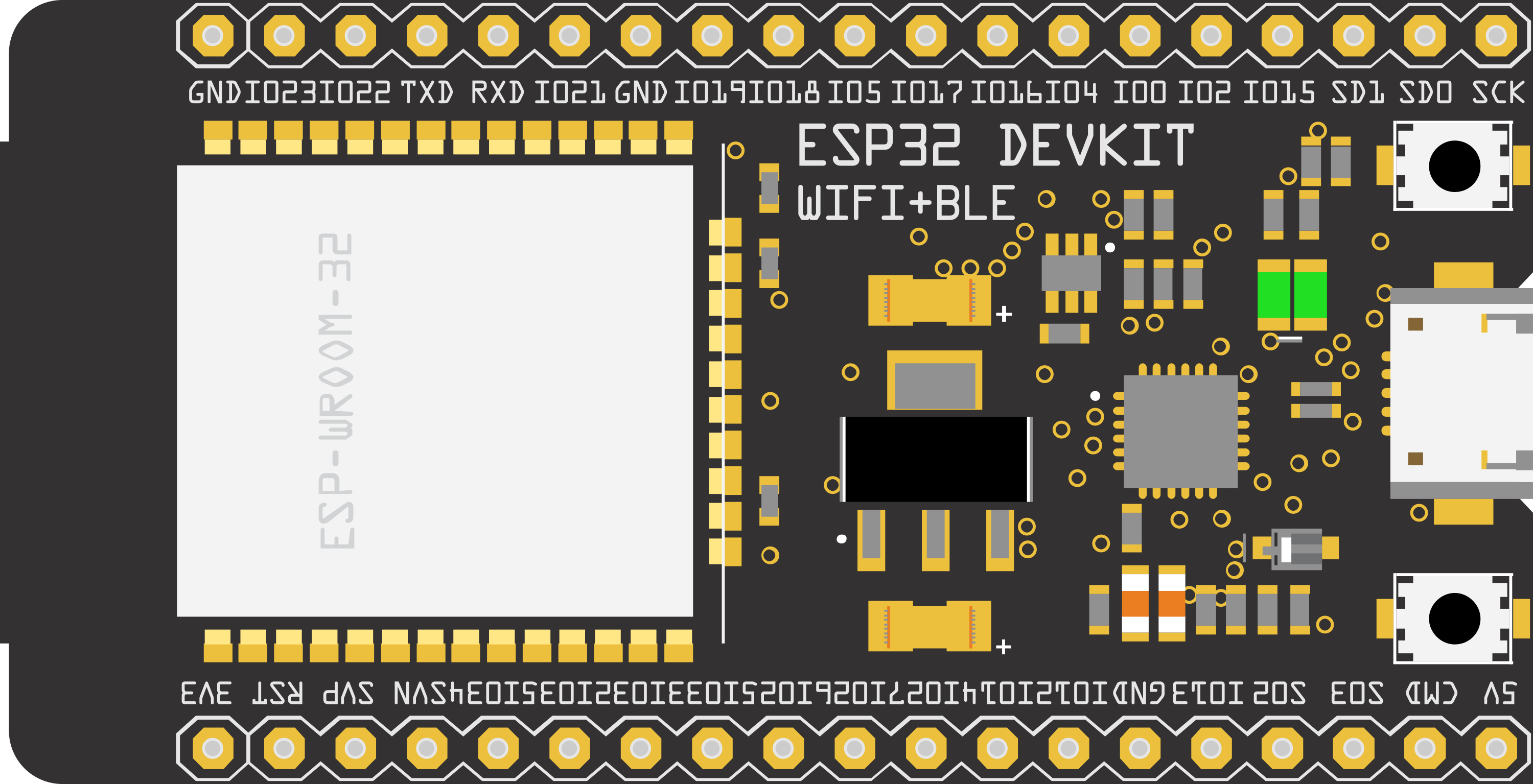
Pin Configuration and Descriptions

Pin Number Name Description
1 3V3 Power supply (3.3V input)
2 GND Ground
3 EN Chip enable (active high)
... ... ...
n IOx General-purpose input/output (x denotes pin number)

Note: This is a partial table. Refer to the ESP32 Wroom datasheet for the complete pinout.

Usage Instructions

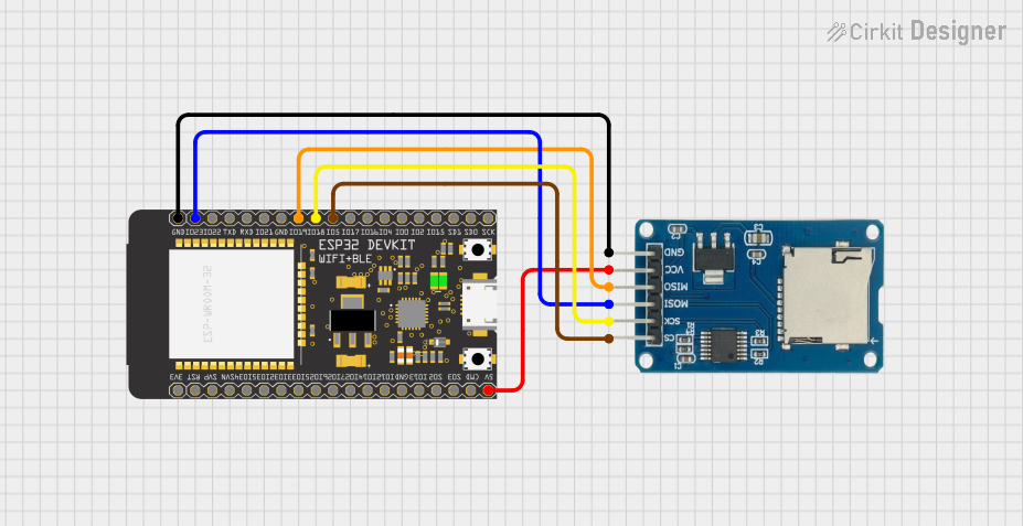
How to Use the Component in a Circuit

  1. Powering the Module: Ensure that the power supply is within the specified range (3.0V to 3.6V). Exceeding the voltage range can damage the module.

  2. Enabling the Chip: The EN pin must be pulled high to enable the chip. It can be connected to the 3V3 pin for automatic enablement on power-up.

  3. Connecting to Wi-Fi or Bluetooth: Utilize the provided libraries in the ESP-IDF or Arduino IDE to connect to wireless networks or Bluetooth devices.

  4. Programming the Module: The ESP32 Wroom can be programmed via the serial interface using the UART bootloader. It is also compatible with the Arduino IDE, which simplifies the development process.

Important Considerations and Best Practices

  • Use a stable power supply to prevent unexpected resets.
  • Ensure proper decoupling with capacitors close to the power pins to smooth out voltage spikes.
  • Avoid drawing more current than the specified maximum from the GPIO pins.
  • Use appropriate logic level shifting when interfacing with components that operate at different voltage levels.

Troubleshooting and FAQs

Common Issues

  • Module Does Not Power On: Check the power supply and connections to the 3V3 and GND pins. Ensure the EN pin is pulled high.
  • Cannot Connect to Wi-Fi or Bluetooth: Verify that the antenna is properly connected and that the correct credentials and protocols are being used in the code.
  • Unexpected Behavior or Resets: Ensure that the power supply is stable and that the GPIO pins are not overloaded.

Solutions and Tips for Troubleshooting

  • Double-check wiring and solder joints for any loose connections or shorts.
  • Use serial output to debug and track down issues in the code.
  • Consult the ESP32 Wroom datasheet and forums for device-specific troubleshooting advice.

FAQs

Q: Can the ESP32 Wroom be used with the Arduino IDE? A: Yes, the ESP32 Wroom is compatible with the Arduino IDE. You will need to install the ESP32 board package to get started.

Q: What is the maximum current that can be drawn from a GPIO pin? A: The maximum current per GPIO pin should not exceed 12 mA.

Q: How do I update the firmware on the ESP32 Wroom? A: Firmware updates can be performed using the UART bootloader and the esptool.py utility or through OTA (Over-The-Air) updates if your code supports it.

Example Code for Arduino UNO

#include <WiFi.h>

// Replace with your network credentials
const char* ssid = "your_SSID";
const char* password = "your_PASSWORD";

void setup() {
  Serial.begin(115200);
  // Connect to Wi-Fi
  WiFi.begin(ssid, password);
  while (WiFi.status() != WL_CONNECTED) {
    delay(500);
    Serial.println("Connecting to WiFi...");
  }
  Serial.println("Connected to WiFi");
}

void loop() {
  // Your code here
}

Note: This example demonstrates how to connect the ESP32 Wroom to a Wi-Fi network. Ensure that you have the ESP32 board package installed in the Arduino IDE to use the WiFi library.

Remember to adhere to the 80-character line length limit for code comments, wrapping text as necessary. This ensures readability and maintainability of the code.