How to Use Arduino Zero MKR: Examples, Pinouts, and Specs
Introduction
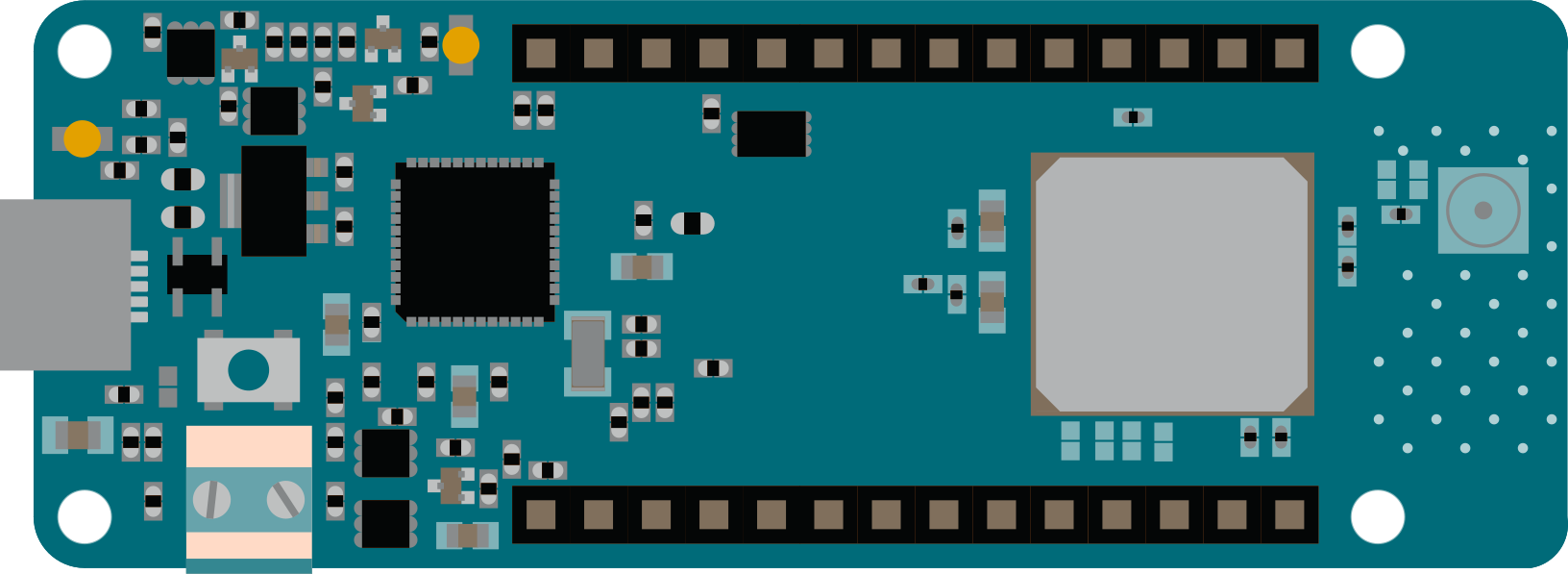
The Arduino Zero MKR is a compact and versatile microcontroller board powered by the SAMD21 ARM Cortex-M0+ processor. Designed specifically for Internet of Things (IoT) applications, it features built-in Wi-Fi and Bluetooth connectivity, making it an excellent choice for projects requiring wireless communication. The board offers a variety of digital and analog I/O pins, enabling seamless integration with sensors, actuators, and other peripherals.
Explore Projects Built with Arduino Zero MKR
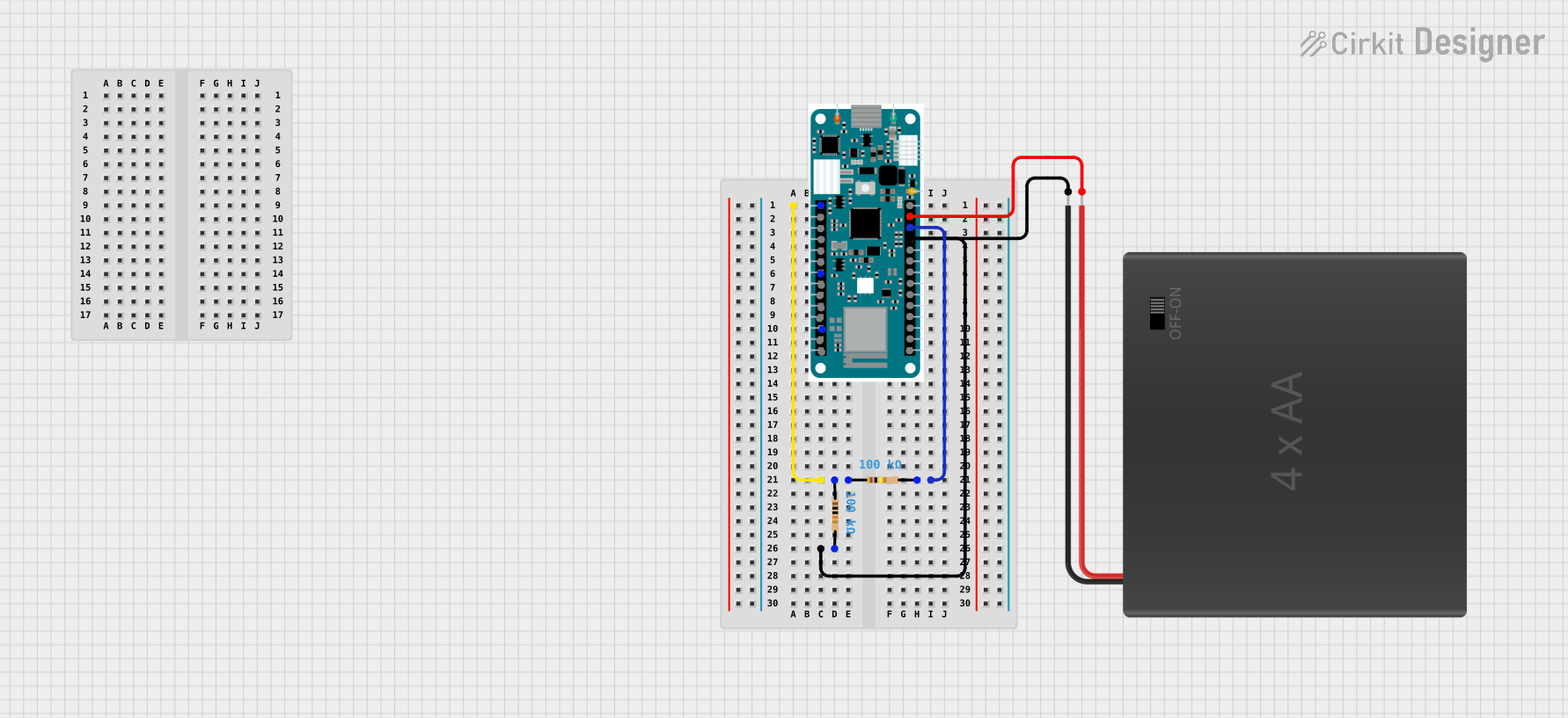
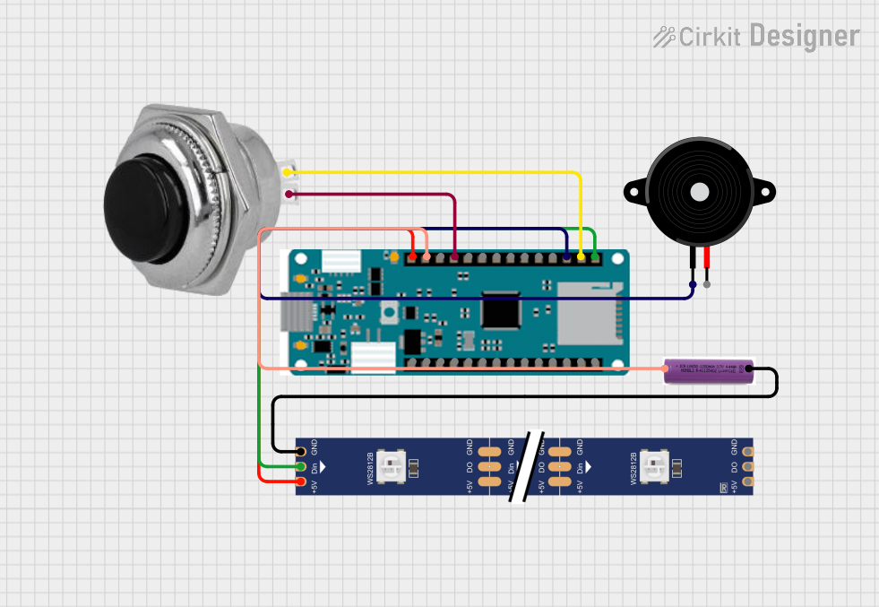
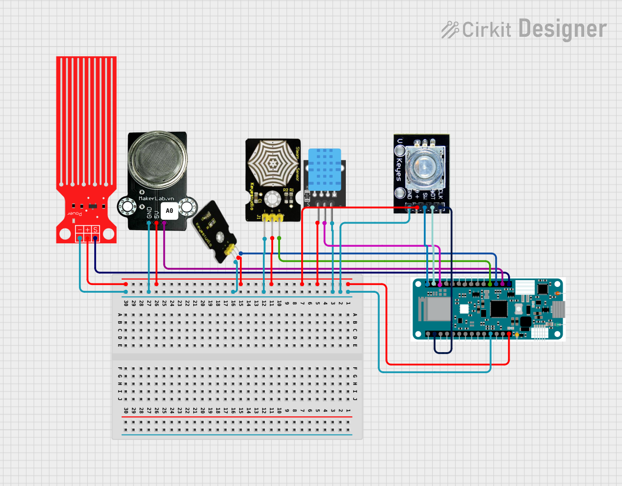
Explore Projects Built with Arduino Zero MKR
Common Applications and Use Cases
- IoT devices and smart home automation
- Wireless sensor networks
- Data logging and remote monitoring
- Prototyping wearable devices
- Educational projects and rapid prototyping
Technical Specifications
Key Technical Details
- Microcontroller: SAMD21 Cortex-M0+ 32-bit ARM MCU
- Operating Voltage: 3.3V
- Input Voltage (via Vin pin): 5V to 6V
- Digital I/O Pins: 8 (of which 4 support PWM)
- Analog Input Pins: 7 (12-bit ADC resolution)
- Analog Output Pins: 1 (10-bit DAC resolution)
- Flash Memory: 256 KB
- SRAM: 32 KB
- Clock Speed: 48 MHz
- Connectivity: Wi-Fi (802.11 b/g/n) and Bluetooth 4.0
- USB Interface: Micro USB
- Dimensions: 61.5 mm x 25 mm
- Weight: 32 g
Pin Configuration and Descriptions
The Arduino Zero MKR features a variety of pins for digital, analog, and communication purposes. Below is a detailed pinout description:
| Pin | Type | Description |
|---|---|---|
| VIN | Power Input | External power input (5V to 6V). |
| 3.3V | Power Output | Regulated 3.3V output for powering external components. |
| GND | Ground | Ground connection. |
| A0-A6 | Analog Input | 12-bit ADC pins for reading analog signals. |
| D0-D7 | Digital I/O | General-purpose digital pins (D3, D4, D5, and D6 support PWM). |
| DAC0 | Analog Output | 10-bit DAC pin for generating analog signals. |
| RX/TX | UART | Serial communication pins (RX for receiving, TX for transmitting). |
| SDA/SCL | I2C | I2C communication pins (SDA for data, SCL for clock). |
| SPI | SPI Interface | SPI communication pins (MISO, MOSI, SCK, and SS). |
| RESET | Reset | Resets the microcontroller. |
Usage Instructions
How to Use the Arduino Zero MKR in a Circuit
Powering the Board:
- Connect the board to a computer or USB power source using a Micro USB cable.
- Alternatively, supply 5V to 6V via the VIN pin for external power.
Connecting Peripherals:
- Use the digital I/O pins (D0-D7) to connect LEDs, buttons, or other digital devices.
- Connect sensors or potentiometers to the analog input pins (A0-A6).
- For communication with other devices, use the UART (RX/TX), I2C (SDA/SCL), or SPI pins.
Programming the Board:
- Install the Arduino IDE from the official Arduino website.
- In the Arduino IDE, select Tools > Board > Arduino MKRZero.
- Connect the board to your computer via USB and select the appropriate COM port.
- Write your code and upload it to the board.
Important Considerations and Best Practices
- Voltage Levels: The Arduino Zero MKR operates at 3.3V. Ensure that any external components connected to the board are compatible with 3.3V logic levels to avoid damage.
- Wi-Fi and Bluetooth: When using wireless communication, ensure that the board is in a location with minimal interference for optimal performance.
- Power Supply: Avoid exceeding the recommended input voltage range (5V to 6V) to prevent damage to the board.
Example Code: Reading an Analog Sensor and Sending Data via Serial
The following example demonstrates how to read an analog sensor connected to pin A0 and send the data to the Serial Monitor.
// Define the analog input pin
const int analogPin = A0;

// Variable to store the sensor value
int sensorValue = 0;

void setup() {
  // Initialize serial communication at 9600 baud
  Serial.begin(9600);
}

void loop() {
  // Read the analog value from the sensor
  sensorValue = analogRead(analogPin);

  // Print the sensor value to the Serial Monitor
  Serial.print("Sensor Value: ");
  Serial.println(sensorValue);

  // Wait for 500 milliseconds before the next reading
  delay(500);
}
Troubleshooting and FAQs
Common Issues and Solutions
The board is not recognized by the computer:
- Ensure that the USB cable is properly connected and functional.
- Verify that the correct board and COM port are selected in the Arduino IDE.
- Try reinstalling the USB drivers for the Arduino Zero MKR.
Wi-Fi or Bluetooth is not working:
- Check that the board is within range of the Wi-Fi network or Bluetooth device.
- Ensure that the correct libraries (e.g.,
WiFiNINA) are installed in the Arduino IDE. - Verify the network credentials in your code.
The board is overheating:
- Confirm that the input voltage does not exceed the recommended range (5V to 6V).
- Avoid drawing excessive current from the 3.3V pin.
FAQs
Can I use 5V sensors with the Arduino Zero MKR?
No, the board operates at 3.3V logic levels. Use a level shifter or voltage divider to interface with 5V sensors.What is the maximum current output of the 3.3V pin?
The 3.3V pin can supply up to 50 mA of current.How do I reset the board?
Press the RESET button on the board or connect the RESET pin to GND momentarily.Can I use the Arduino Zero MKR with batteries?
Yes, you can power the board using a 3.7V Li-Po battery connected to the appropriate battery connector (if available).