How to Use PT100: Examples, Pinouts, and Specs
Introduction
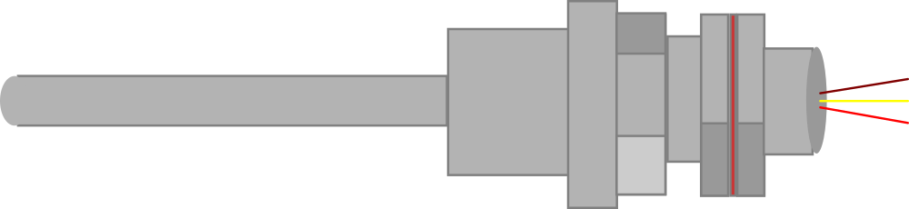
The PT100 is a precision temperature sensing device that utilizes the predictable change in electrical resistance of platinum correlating to temperature. It is a Resistance Temperature Detector (RTD) with a nominal resistance of 100 ohms at 0°C. PT100 sensors are widely used in industrial and laboratory applications due to their high accuracy, long-term stability, and repeatability.
Explore Projects Built with PT100

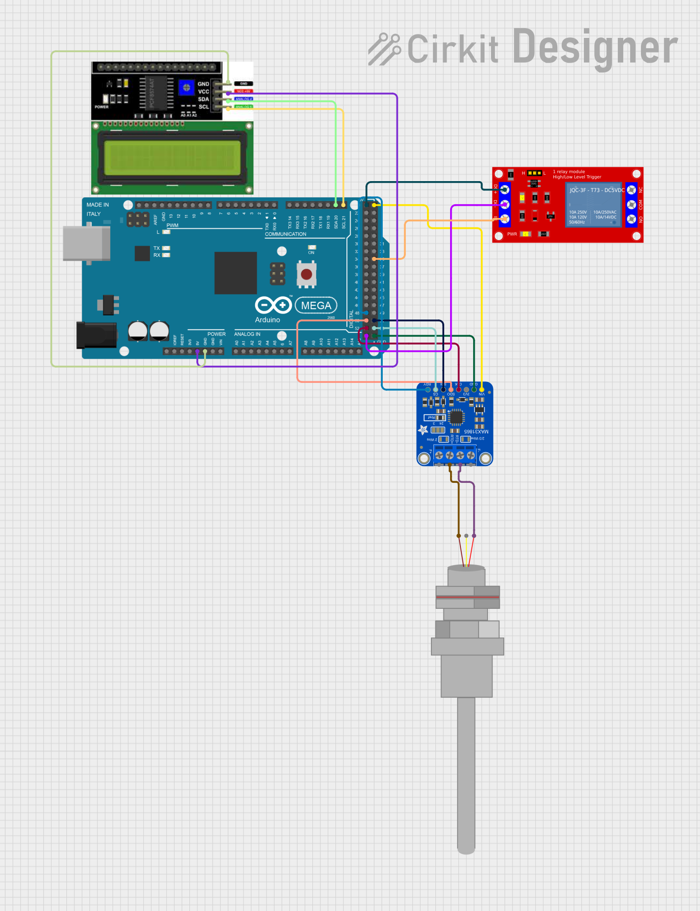

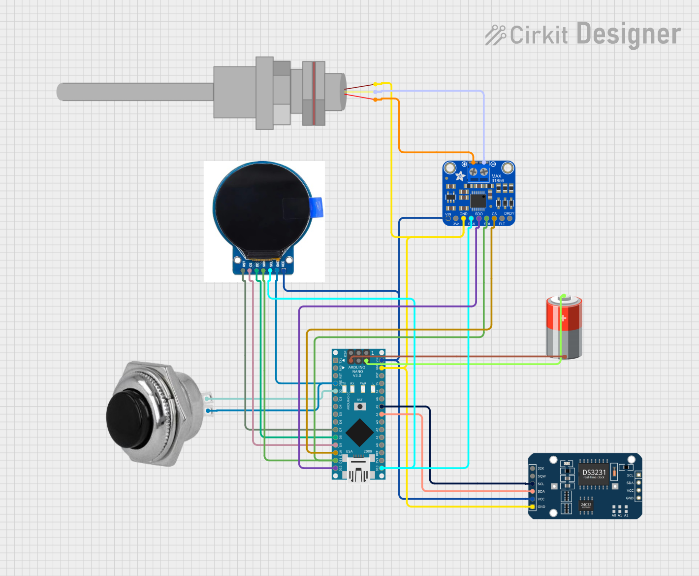
Explore Projects Built with PT100
Common Applications and Use Cases
- Industrial process control
- HVAC systems
- Automotive industry
- Laboratory and research
- Food processing equipment
- Electronics monitoring
Technical Specifications
Key Technical Details
- Base Resistance: 100 ohms at 0°C
- Temperature Coefficient: Approximately 0.385 ohms/°C
- Temperature Range: Typically -200°C to +850°C
- Accuracy: Depends on the class of the sensor (e.g., Class A, B)
- Stability: High long-term stability
Pin Configuration and Descriptions
| Pin Number | Description |
|---|---|
| 1 | RTD lead 1 |
| 2 | RTD lead 2 (optional) |
| 3 | RTD lead 3 (optional) |
Note: PT100 sensors can come in 2-wire, 3-wire, or 4-wire configurations. The table above shows a simplified 2-wire configuration.
Usage Instructions
How to Use the PT100 in a Circuit
- Choose the Right Configuration: Select a 2-wire, 3-wire, or 4-wire PT100 based on the accuracy required and the measurement system.
- Connect to a Measurement Device: Use a precision analog-to-digital converter (ADC) or a dedicated RTD input that can measure resistance accurately.
- Provide a Constant Current Source: To measure the resistance, pass a constant current through the PT100 and measure the voltage across it.
- Calculate Temperature: Use the measured resistance and the RTD's characteristic equation to calculate the temperature.
Important Considerations and Best Practices
- Lead Resistance Compensation: For higher accuracy, especially in long cable runs, use a 3-wire or 4-wire PT100 to compensate for lead resistance.
- Avoid Self-Heating: Pass a low current through the PT100 to prevent self-heating, which can affect the measurement.
- Use Shielded Cables: To minimize electrical noise, use shielded cables, especially in industrial environments.
- Calibration: Regularly calibrate the PT100 sensor to maintain accuracy.
Troubleshooting and FAQs
Common Issues
- Inaccurate Temperature Readings: This can be due to incorrect wiring, self-heating, or a faulty sensor.
- Drift Over Time: The sensor may need recalibration or replacement if it shows significant drift.
Solutions and Tips for Troubleshooting
- Check Wiring Connections: Ensure all connections are secure and correct for the sensor's configuration.
- Verify Current Source: Confirm that the current source is stable and at the correct level.
- Inspect for Damage: Look for any physical damage to the sensor or wires that could affect performance.
FAQs
Q: Can I use a PT100 sensor with an Arduino UNO? A: Yes, but you will need additional circuitry, such as an ADC with RTD support or an RTD-to-digital converter module.
Q: How often should I calibrate my PT100 sensor? A: Calibration frequency depends on the usage conditions and required accuracy. It is typically recommended to calibrate annually or after any mechanical shock or exposure to extreme temperatures.
Q: What is the difference between a 2-wire and a 4-wire PT100? A: A 2-wire PT100 has the simplest configuration but is most susceptible to lead resistance errors. A 4-wire PT100 offers the best accuracy by completely eliminating the effect of lead resistance.
Example Arduino UNO Code
Below is an example of how to interface a PT100 sensor with an Arduino UNO using a MAX31865 RTD-to-digital converter module.
#include <SPI.h>
#include <Adafruit_MAX31865.h>

// Use software SPI: CS, DI, DO, CLK
Adafruit_MAX31865 max = Adafruit_MAX31865(10, 11, 12, 13);
// or use hardware SPI, just pass in the CS pin
//Adafruit_MAX31865 max = Adafruit_MAX31865(10);

void setup() {
  Serial.begin(115200);
  Serial.println("MAX31865 PT100 Sensor Test");

  max.begin(MAX31865_3WIRE);  // Set to 2WIRE or 4WIRE as needed
}

void loop() {
  uint16_t rtd = max.readRTD();

  Serial.print("RTD value: "); Serial.println(rtd);
  float ratio = rtd;
  ratio /= 32768;
  Serial.print("Ratio = "); Serial.println(ratio, 8);
  Serial.print("Resistance = "); Serial.println(RREF * ratio, 8);
  Serial.print("Temperature = "); Serial.println(max.temperature(RNOMINAL, RREF));

  // Check and print any faults
  uint8_t fault = max.readFault();
  if (fault) {
    Serial.print("Fault 0x"); Serial.println(fault, HEX);
    if (fault & MAX31865_FAULT_HIGHTHRESH) {
      Serial.println("RTD High Threshold");
    }
    if (fault & MAX31865_FAULT_LOWTHRESH) {
      Serial.println("RTD Low Threshold");
    }
    if (fault & MAX31865_FAULT_REFINLOW) {
      Serial.println("REFIN- > 0.85 x Bias");
    }
    if (fault & MAX31865_FAULT_REFINHIGH) {
      Serial.println("REFIN- < 0.85 x Bias - FORCE- open");
    }
    if (fault & MAX31865_FAULT_RTDINLOW) {
      Serial.println("RTDIN- < 0.85 x Bias - FORCE- open");
    }
    if (fault & MAX31865_FAULT_OVUV) {
      Serial.println("Under/Over voltage");
    }
    max.clearFault();
  }
  Serial.println();
  delay(1000);
}
Note: The above code uses the Adafruit_MAX31865 library to interface with the MAX31865 module. Make sure to install the library before compiling the code. The RREF and RNOMINAL constants should be set according to your specific hardware setup.
This documentation provides a comprehensive guide to using the PT100 sensor. For further assistance, consult the manufacturer's datasheet and application notes.