Cirkit Designer Logo
Cirkit Designer
Your all-in-one circuit design IDE
Home / 
Component Documentation

How to Use TWS-434 Transmitter: Examples, Pinouts, and Specs

Image of TWS-434 Transmitter
Cirkit Designer LogoDesign with TWS-434 Transmitter in Cirkit Designer

Introduction

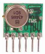
The TWS-434 is a low-power wireless transmitter module manufactured by WEN SHING. It operates in the 434 MHz frequency band and is designed for short-range communication. This module is widely used in applications such as remote controls, wireless sensor networks, home automation systems, and other embedded systems requiring wireless data transmission.

The TWS-434 is compact, cost-effective, and easy to integrate into various projects, making it a popular choice for hobbyists and professionals alike.

Explore Projects Built with TWS-434 Transmitter

Use Cirkit Designer to design, explore, and prototype these projects online. Some projects support real-time simulation. Click "Open Project" to start designing instantly!
ESP32-Based RF Communication System with 433 MHz Modules
Image of 433 mhz: A project utilizing TWS-434 Transmitter in a practical application
This circuit comprises an ESP32 microcontroller connected to a 433 MHz RF transmitter and receiver pair. The ESP32 is programmed to receive and decode RF signals through the receiver module, as well as send RF signals via the transmitter module. Additionally, the ESP32 can communicate with a Bluetooth device to exchange commands and data, and it uses an LED for status indication.
Cirkit Designer LogoOpen Project in Cirkit Designer
433 MHz RF Transmitter and Receiver with Arduino UNO for Wireless Communication
Image of Wireless Communication: A project utilizing TWS-434 Transmitter in a practical application
This circuit consists of two Arduino UNO microcontrollers, each connected to an RF 433 MHz Transmitter and a 433 MHz RF Receiver Module. The setup allows for wireless communication between the two Arduinos, enabling them to send and receive data over a 433 MHz RF link.
Cirkit Designer LogoOpen Project in Cirkit Designer
Battery-Powered nRF52840 and HT-RA62 Communication Module
Image of NRF52840+HT-RA62: A project utilizing TWS-434 Transmitter in a practical application
This circuit is a wireless communication system powered by a 18650 Li-ion battery, featuring an nRF52840 ProMicro microcontroller and an HT-RA62 transceiver module. The nRF52840 handles the control logic and interfaces with the HT-RA62 for data transmission, while the battery provides the necessary power for the entire setup.
Cirkit Designer LogoOpen Project in Cirkit Designer
ESP32-Controlled FM Radio Transmitter
Image of bluetooth: A project utilizing TWS-434 Transmitter in a practical application
This circuit features an ESP32 microcontroller connected to a DSP PLL Stereo FM Transmitter, with the ESP32's digital pin D26 interfacing with the transmitter's auxiliary input. The ESP32 and the FM transmitter are configured for serial communication via the ESP32's TX0 to the transmitter's RX and RX0 to the transmitter's TX. The circuit is powered by a 5V battery, with the ESP32's Vin and GND connected to the battery's positive and negative terminals, respectively, and the FM transmitter's Vcc and Ground also connected to the ESP32's 3V3 and GND. An antenna is connected to the FM transmitter for signal broadcasting.
Cirkit Designer LogoOpen Project in Cirkit Designer

Explore Projects Built with TWS-434 Transmitter

Use Cirkit Designer to design, explore, and prototype these projects online. Some projects support real-time simulation. Click "Open Project" to start designing instantly!
Image of 433 mhz: A project utilizing TWS-434 Transmitter in a practical application
ESP32-Based RF Communication System with 433 MHz Modules
This circuit comprises an ESP32 microcontroller connected to a 433 MHz RF transmitter and receiver pair. The ESP32 is programmed to receive and decode RF signals through the receiver module, as well as send RF signals via the transmitter module. Additionally, the ESP32 can communicate with a Bluetooth device to exchange commands and data, and it uses an LED for status indication.
Cirkit Designer LogoOpen Project in Cirkit Designer
Image of Wireless Communication: A project utilizing TWS-434 Transmitter in a practical application
433 MHz RF Transmitter and Receiver with Arduino UNO for Wireless Communication
This circuit consists of two Arduino UNO microcontrollers, each connected to an RF 433 MHz Transmitter and a 433 MHz RF Receiver Module. The setup allows for wireless communication between the two Arduinos, enabling them to send and receive data over a 433 MHz RF link.
Cirkit Designer LogoOpen Project in Cirkit Designer
Image of NRF52840+HT-RA62: A project utilizing TWS-434 Transmitter in a practical application
Battery-Powered nRF52840 and HT-RA62 Communication Module
This circuit is a wireless communication system powered by a 18650 Li-ion battery, featuring an nRF52840 ProMicro microcontroller and an HT-RA62 transceiver module. The nRF52840 handles the control logic and interfaces with the HT-RA62 for data transmission, while the battery provides the necessary power for the entire setup.
Cirkit Designer LogoOpen Project in Cirkit Designer
Image of bluetooth: A project utilizing TWS-434 Transmitter in a practical application
ESP32-Controlled FM Radio Transmitter
This circuit features an ESP32 microcontroller connected to a DSP PLL Stereo FM Transmitter, with the ESP32's digital pin D26 interfacing with the transmitter's auxiliary input. The ESP32 and the FM transmitter are configured for serial communication via the ESP32's TX0 to the transmitter's RX and RX0 to the transmitter's TX. The circuit is powered by a 5V battery, with the ESP32's Vin and GND connected to the battery's positive and negative terminals, respectively, and the FM transmitter's Vcc and Ground also connected to the ESP32's 3V3 and GND. An antenna is connected to the FM transmitter for signal broadcasting.
Cirkit Designer LogoOpen Project in Cirkit Designer

Technical Specifications

Below are the key technical details of the TWS-434 transmitter module:

Parameter Value
Operating Frequency 434 MHz
Operating Voltage 3.3V to 12V DC
Operating Current 10 mA (typical)
Transmission Range Up to 500 feet (line of sight)
Modulation Type Amplitude Shift Keying (ASK)
Data Rate Up to 10 kbps
Operating Temperature -20°C to +70°C
Dimensions 19mm x 19mm x 7mm

Pin Configuration and Descriptions

The TWS-434 module has four pins, as described in the table below:

Pin Number Pin Name Description
1 VCC Power supply input (3.3V to 12V DC).
2 DATA Data input pin. Connect this to the microcontroller or data source.
3 GND Ground connection.
4 ANT Antenna connection. Attach a 17 cm wire or a suitable 434 MHz antenna here.

Usage Instructions

How to Use the TWS-434 in a Circuit

  1. Power Supply: Connect the VCC pin to a regulated power supply (3.3V to 12V DC). Ensure the power source is stable to avoid transmission issues.
  2. Data Input: Connect the DATA pin to the output of a microcontroller, encoder, or other data source. The module transmits the data it receives on this pin.
  3. Ground Connection: Connect the GND pin to the ground of your circuit.
  4. Antenna: Attach a 17 cm wire or a pre-made 434 MHz antenna to the ANT pin for optimal transmission range.

Important Considerations and Best Practices

  • Antenna Placement: Ensure the antenna is placed away from metal objects or other components that may interfere with the signal.
  • Power Supply Noise: Use a decoupling capacitor (e.g., 0.1 µF) near the VCC pin to filter out noise from the power supply.
  • Data Encoding: For reliable communication, use an encoder (e.g., HT12E) to encode the data before transmitting it.
  • Line of Sight: The module performs best in line-of-sight conditions. Obstacles like walls or furniture may reduce the transmission range.

Example: Connecting TWS-434 to an Arduino UNO

Below is an example of how to use the TWS-434 with an Arduino UNO to transmit data:

Circuit Connections

  • Connect the VCC pin of the TWS-434 to the 5V pin on the Arduino.
  • Connect the GND pin of the TWS-434 to the GND pin on the Arduino.
  • Connect the DATA pin of the TWS-434 to digital pin 12 on the Arduino.
  • Attach a 17 cm wire to the ANT pin of the TWS-434.

Arduino Code

// TWS-434 Transmitter Example Code
// This code sends a simple HIGH/LOW signal to the TWS-434 module.

#define DATA_PIN 12  // Define the pin connected to the DATA pin of TWS-434

void setup() {
  pinMode(DATA_PIN, OUTPUT);  // Set the DATA pin as an output
}

void loop() {
  digitalWrite(DATA_PIN, HIGH);  // Send a HIGH signal
  delay(1000);                   // Wait for 1 second
  digitalWrite(DATA_PIN, LOW);   // Send a LOW signal
  delay(1000);                   // Wait for 1 second
}

Notes:

  • The above code sends a simple HIGH/LOW signal. For more complex data transmission, consider using an encoder/decoder pair (e.g., HT12E/HT12D).
  • Ensure the receiver module (e.g., RWS-434) is properly configured to receive the transmitted signal.

Troubleshooting and FAQs

Common Issues and Solutions

  1. No Signal Transmission

    • Cause: Incorrect wiring or power supply issues.
    • Solution: Double-check all connections and ensure the power supply voltage is within the specified range (3.3V to 12V).
  2. Short Transmission Range

    • Cause: Poor antenna placement or interference.
    • Solution: Use a 17 cm wire as the antenna and ensure it is placed away from obstructions or interference sources.
  3. Data Corruption

    • Cause: Noise or lack of data encoding.
    • Solution: Use an encoder (e.g., HT12E) to encode the data before transmission.
  4. Interference with Other Devices

    • Cause: Operating in a crowded frequency band.
    • Solution: Ensure the module is used in an environment with minimal interference. Avoid using multiple transmitters on the same frequency.

FAQs

Q1: Can I use the TWS-434 with a 3.3V microcontroller?
A1: Yes, the TWS-434 can operate with a 3.3V power supply. Ensure the data signal from the microcontroller is also 3.3V compatible.

Q2: What is the maximum data rate supported by the TWS-434?
A2: The TWS-434 supports a maximum data rate of 10 kbps.

Q3: Can I use the TWS-434 without an antenna?
A3: While the module may work without an antenna, the transmission range will be significantly reduced. It is recommended to use a 17 cm wire or a suitable 434 MHz antenna.

Q4: Is the TWS-434 compatible with the RWS-434 receiver module?
A4: Yes, the TWS-434 is designed to work seamlessly with the RWS-434 receiver module for wireless communication.

By following this documentation, you can effectively integrate the TWS-434 transmitter module into your projects and troubleshoot common issues.