How to Use Adafruit LM4040 Voltage Reference : Examples, Pinouts, and Specs
Introduction
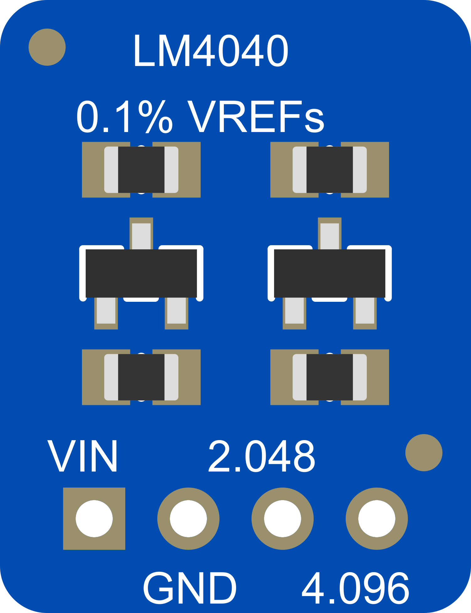
The Adafruit LM4040 is a precision voltage reference breakout board that provides a fixed voltage reference of high stability and accuracy. This component is commonly used in analog-to-digital conversion (ADC) applications, calibration of systems, and any circuit requiring a precise reference voltage.
Explore Projects Built with Adafruit LM4040 Voltage Reference
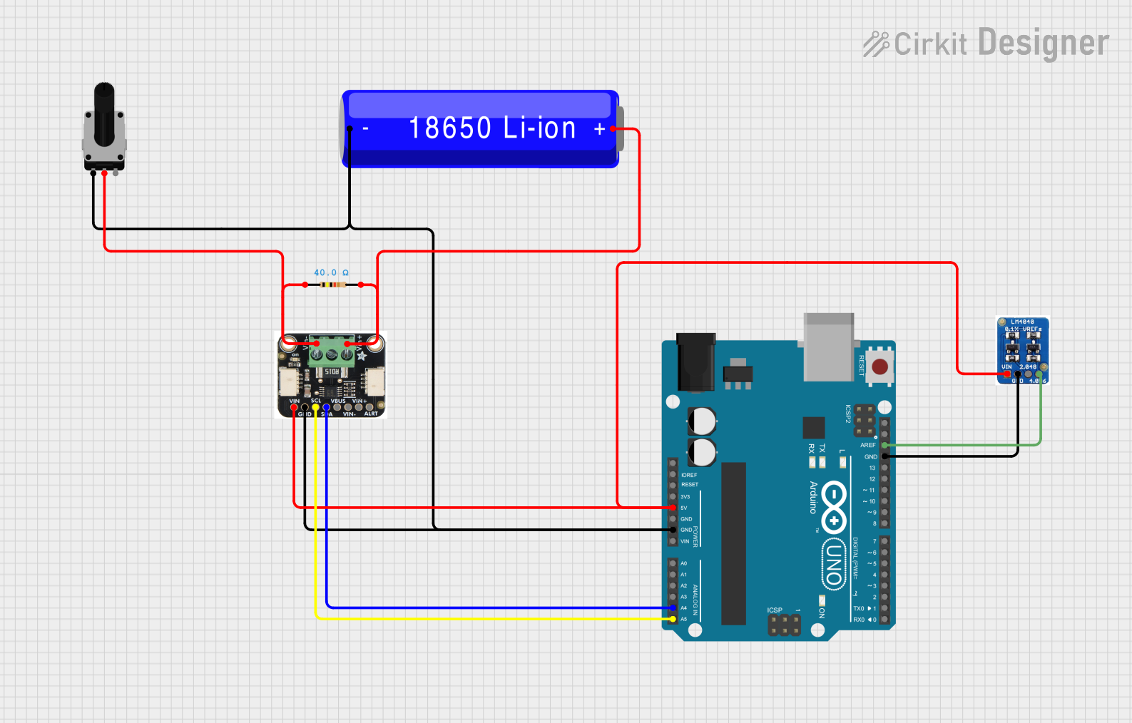

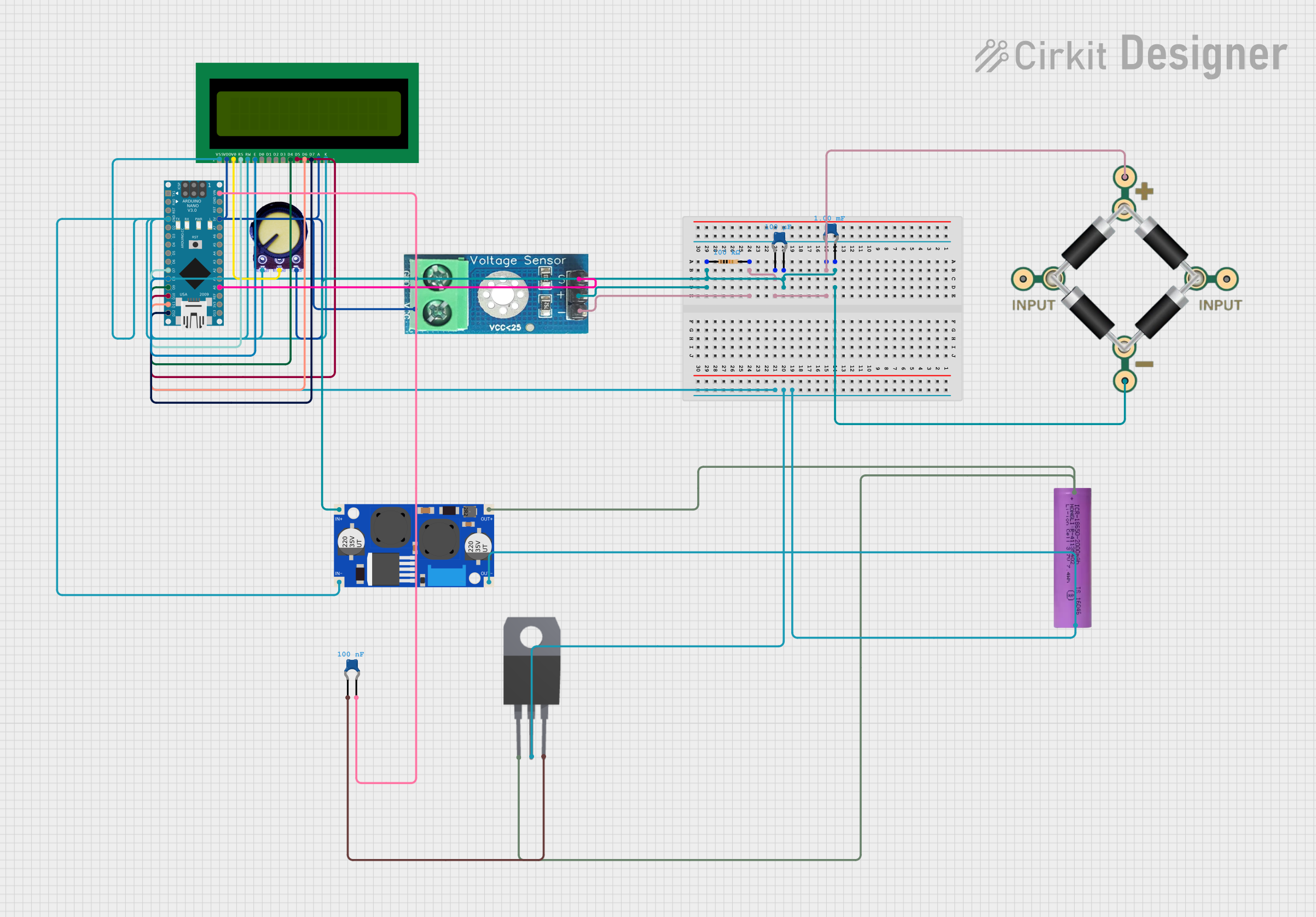
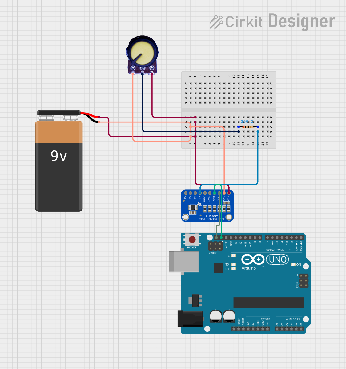
Explore Projects Built with Adafruit LM4040 Voltage Reference
Common Applications and Use Cases
- ADC reference voltage
- Battery-operated equipment calibration
- Voltage monitoring
- Portable instrumentation
- Data acquisition systems
Technical Specifications
The Adafruit LM4040 Voltage Reference Breakout provides a stable reference voltage with the following key specifications:
- Nominal Output Voltage: 2.048V, 4.096V (depending on model)
- Initial Accuracy: ±0.1%
- Temperature Coefficient: 100 ppm/°C (max)
- Operating Current: 60 µA to 15 mA
- Operating Temperature Range: -40°C to +85°C
Pin Configuration and Descriptions
| Pin Number | Name | Description |
|---|---|---|
| 1 | VIN | Input voltage (5V recommended) |
| 2 | GND | Ground |
| 3 | VOUT | Fixed reference voltage output |
Usage Instructions
How to Use the Component in a Circuit
- Connect the VIN pin to a 5V power supply.
- Connect the GND pin to the ground of your power supply.
- The VOUT pin will now provide a stable reference voltage that can be used in your circuit.
Important Considerations and Best Practices
- Ensure that the input voltage does not exceed the maximum rating to prevent damage.
- The output voltage is fixed and cannot be adjusted.
- For best performance, bypass the VIN pin with a 0.1 µF ceramic capacitor to ground.
- Keep the leads as short as possible to minimize noise and voltage drop.
Example Connection with Arduino UNO
// Define the analog pin connected to the VOUT of the LM4040
const int referencePin = A0;

void setup() {
  // Initialize serial communication at 9600 baud rate
  Serial.begin(9600);
}

void loop() {
  // Read the voltage on the reference pin
  int sensorValue = analogRead(referencePin);
  // Convert the analog reading to voltage
  float voltage = sensorValue * (5.0 / 1023.0);
  // Print the voltage to the Serial Monitor
  Serial.println(voltage);
  // Wait for a second
  delay(1000);
}
This code reads the voltage from the LM4040 connected to the A0 pin on the Arduino UNO and prints the value to the Serial Monitor.
Troubleshooting and FAQs
Common Issues Users Might Face
- Inaccurate Output Voltage: Ensure that the input voltage is stable and within the recommended range. Check for proper grounding and low-noise environment.
- No Output Voltage: Verify that the breakout board is correctly powered and that all connections are secure. Check for any signs of physical damage to the board.
Solutions and Tips for Troubleshooting
- If the output voltage is unstable, add a bypass capacitor between VIN and GND.
- Use a multimeter to check the continuity of the connections.
- Ensure that the Arduino board is functioning correctly by testing it with another known-good component.
FAQs
Q: Can I use the LM4040 with a 3.3V system? A: Yes, the LM4040 can be used with a 3.3V system, but ensure that the input voltage is sufficient to maintain the accuracy of the output voltage.
Q: What is the purpose of the bypass capacitor? A: The bypass capacitor helps filter out noise from the power supply, providing a cleaner input voltage to the LM4040.
Q: How do I calibrate my ADC with the LM4040? A: Use the precise voltage output from the LM4040 as a reference to calibrate the ADC readings in your microcontroller's software.
Q: Is the LM4040 affected by temperature changes? A: The LM4040 has a low temperature coefficient, but extreme temperature changes can still affect the output voltage slightly. Always consider the operating temperature range for best performance.
For further assistance, contact Adafruit customer support or refer to the community forums for shared experiences and solutions from other users.