How to Use Signal Tower with buzzer: Examples, Pinouts, and Specs
Introduction
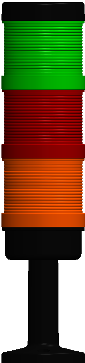
The Signal Tower with Buzzer is a versatile visual and auditory signaling device commonly used in industrial and commercial environments. It features a series of colored lights (e.g., red, yellow, green) and an integrated buzzer to provide clear status indications or alerts. This component is ideal for applications requiring real-time status monitoring, such as factory automation, machine status indication, and safety alerts.
Explore Projects Built with Signal Tower with buzzer
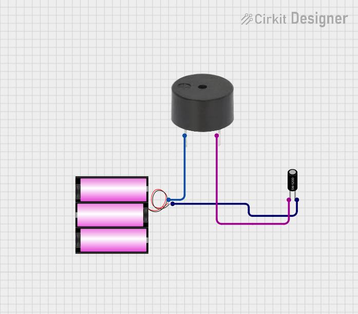
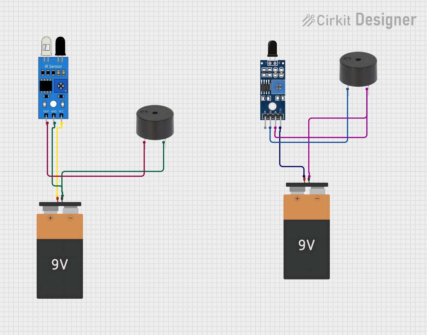
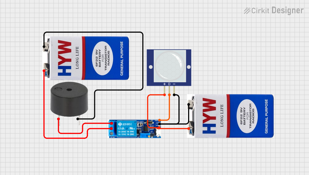

Explore Projects Built with Signal Tower with buzzer
Common Applications:
- Factory automation systems to indicate machine status (e.g., running, idle, error).
- Safety alerts in industrial environments.
- Process monitoring in assembly lines.
- Commercial use in public spaces for notifications or warnings.
Technical Specifications
Below are the key technical details of the Signal Tower with Buzzer:
| Parameter | Value |
|---|---|
| Operating Voltage | 12V DC or 24V DC (model-dependent) |
| Current Consumption | 50-200 mA (varies by light/buzzer) |
| Light Colors | Red, Yellow, Green (standard) |
| Buzzer Sound Level | 85-100 dB |
| Mounting Style | Pole or direct mount |
| Operating Temperature | -10°C to 50°C |
| Housing Material | ABS Plastic (flame-resistant) |
| IP Rating | IP54 (dust and splash resistant) |
Pin Configuration and Descriptions
The Signal Tower with Buzzer typically has multiple wires for control. Below is the pin configuration:
| Wire Color | Function |
|---|---|
| Red | Power supply for the red light |
| Yellow | Power supply for the yellow light |
| Green | Power supply for the green light |
| Black | Common ground (GND) |
| White | Power supply for the buzzer |
Usage Instructions
How to Use the Signal Tower with Buzzer in a Circuit
- Power Supply: Ensure the power supply matches the operating voltage of the signal tower (e.g., 12V DC or 24V DC). Exceeding the voltage rating may damage the component.
- Wiring: Connect the black wire to the ground (GND) of your power source. Then, connect the red, yellow, green, and white wires to their respective control signals or switches.
- Control Signals: Use switches, relays, or microcontroller GPIO pins to control the lights and buzzer. Activating a wire (e.g., applying voltage) will turn on the corresponding light or buzzer.
Important Considerations and Best Practices
- Current Limiting: If using a microcontroller (e.g., Arduino UNO), ensure the GPIO pins are not overloaded. Use transistors or relays to handle the current required by the signal tower.
- Polarity: Double-check the polarity of the connections to avoid damage.
- Environment: Install the signal tower in a location that is within its operating temperature range and protected from excessive moisture or dust.
Example: Connecting to an Arduino UNO
Below is an example of how to connect and control the Signal Tower with Buzzer using an Arduino UNO:
Circuit Setup:
- Connect the black wire (GND) to the Arduino's GND pin.
- Connect the red, yellow, green, and white wires to Arduino digital pins (e.g., D3, D4, D5, D6) through NPN transistors or relays.
Arduino Code:
// Define pin connections for the signal tower
const int redLightPin = 3;    // Red light control pin
const int yellowLightPin = 4; // Yellow light control pin
const int greenLightPin = 5;  // Green light control pin
const int buzzerPin = 6;      // Buzzer control pin

void setup() {
  // Set pins as outputs
  pinMode(redLightPin, OUTPUT);
  pinMode(yellowLightPin, OUTPUT);
  pinMode(greenLightPin, OUTPUT);
  pinMode(buzzerPin, OUTPUT);
}

void loop() {
  // Example sequence: Red light and buzzer on for 1 second
  digitalWrite(redLightPin, HIGH);
  digitalWrite(buzzerPin, HIGH);
  delay(1000);

  // Turn off red light and buzzer, turn on yellow light for 1 second
  digitalWrite(redLightPin, LOW);
  digitalWrite(buzzerPin, LOW);
  digitalWrite(yellowLightPin, HIGH);
  delay(1000);

  // Turn off yellow light, turn on green light for 1 second
  digitalWrite(yellowLightPin, LOW);
  digitalWrite(greenLightPin, HIGH);
  delay(1000);

  // Turn off green light
  digitalWrite(greenLightPin, LOW);
}
Notes:
- Use appropriate resistors or transistors to protect the Arduino pins.
- The buzzer can be activated independently or in combination with the lights.
Troubleshooting and FAQs
Common Issues and Solutions
Lights or Buzzer Not Working:
- Cause: Incorrect wiring or insufficient power supply.
- Solution: Verify all connections and ensure the power supply matches the component's voltage rating.
Microcontroller Pins Overheating:
- Cause: Directly driving the signal tower without current-limiting components.
- Solution: Use transistors or relays to handle the current load.
Buzzer Too Loud:
- Cause: The buzzer's sound level is fixed and may be too loud for certain environments.
- Solution: Use a resistor in series with the buzzer wire to reduce the current and lower the sound level.
Signal Tower Not Responding to Control Signals:
- Cause: Incorrect GPIO pin configuration or damaged wires.
- Solution: Check the Arduino code and ensure the pins are set as outputs. Inspect the wires for damage.
FAQs
Q: Can I use the Signal Tower with Buzzer outdoors?
A: The component has an IP54 rating, which provides limited protection against dust and splashes. For outdoor use, additional weatherproofing is recommended.
Q: Can I control the lights and buzzer simultaneously?
A: Yes, you can activate multiple wires at the same time to control the lights and buzzer simultaneously.
Q: What is the maximum wire length for installation?
A: For optimal performance, keep the wire length under 10 meters to minimize voltage drop. Use thicker wires for longer distances.
Q: Can I use a 5V power supply?
A: No, the Signal Tower with Buzzer requires a 12V or 24V power supply, depending on the model. Using a 5V supply will not provide sufficient power.