Cirkit Designer Logo
Cirkit Designer
Your all-in-one circuit design IDE
Home / 
Component Documentation

How to Use LD2410: Examples, Pinouts, and Specs

Image of LD2410
Cirkit Designer LogoDesign with LD2410 in Cirkit Designer

Introduction

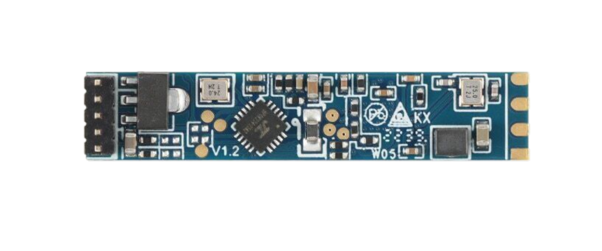
The LD2410 is a microwave radar sensor module designed for motion detection and presence sensing. Operating in the 24 GHz frequency band, this sensor is highly effective in various applications, including security systems, lighting control, and automation. Its ability to detect motion through non-metallic materials makes it a versatile choice for both indoor and outdoor use.

Explore Projects Built with LD2410

Use Cirkit Designer to design, explore, and prototype these projects online. Some projects support real-time simulation. Click "Open Project" to start designing instantly!
ESP32-Based Environmental Sensing Station with Wi-Fi and Light Intensity Measurement
Image of multi esp32: A project utilizing LD2410 in a practical application
This circuit is designed to collect environmental data and light intensity measurements using the ESP32 microcontroller, which communicates with a BME/BMP280 sensor and a BH1750 sensor via I2C, and transmits the data through an LD2410C communication module using serial communication.
Cirkit Designer LogoOpen Project in Cirkit Designer
Battery-Powered DC Motor Control with USB Charging and LED Indicator
Image of lumantas: A project utilizing LD2410 in a practical application
This circuit is designed to charge a Li-ion battery and power a DC motor and a 12V LED. The TP4056 module manages the battery charging process, while the PowerBoost 1000 and MT3608 boost converters step up the voltage to drive the motor and LED, respectively. Two rocker switches control the power flow to the LED and the charging circuit.
Cirkit Designer LogoOpen Project in Cirkit Designer
Cellular-Enabled IoT Device with Real-Time Clock and Power Management
Image of LRCM PHASE 2 BASIC: A project utilizing LD2410 in a practical application
This circuit features a LilyGo-SIM7000G module for cellular communication and GPS functionality, interfaced with an RTC DS3231 for real-time clock capabilities. It includes voltage sensing through two voltage sensor modules, and uses an 8-channel opto-coupler for isolating different parts of the circuit. Power management is handled by a buck converter connected to a DC power source and batteries, with a fuse for protection and a rocker switch for on/off control. Additionally, there's an LED for indication purposes.
Cirkit Designer LogoOpen Project in Cirkit Designer
Solar-Powered LED Light with Battery Charging and Light Sensing
Image of ebt: A project utilizing LD2410 in a practical application
This circuit is a solar-powered battery charging and LED lighting system. The solar cell charges a 18650 Li-ion battery through a TP4056 charging module, which also powers a 7805 voltage regulator to provide a stable 5V output. A photocell and MOSFET control the power to a high-power LED, allowing it to turn on or off based on ambient light conditions.
Cirkit Designer LogoOpen Project in Cirkit Designer

Explore Projects Built with LD2410

Use Cirkit Designer to design, explore, and prototype these projects online. Some projects support real-time simulation. Click "Open Project" to start designing instantly!
Image of multi esp32: A project utilizing LD2410 in a practical application
ESP32-Based Environmental Sensing Station with Wi-Fi and Light Intensity Measurement
This circuit is designed to collect environmental data and light intensity measurements using the ESP32 microcontroller, which communicates with a BME/BMP280 sensor and a BH1750 sensor via I2C, and transmits the data through an LD2410C communication module using serial communication.
Cirkit Designer LogoOpen Project in Cirkit Designer
Image of lumantas: A project utilizing LD2410 in a practical application
Battery-Powered DC Motor Control with USB Charging and LED Indicator
This circuit is designed to charge a Li-ion battery and power a DC motor and a 12V LED. The TP4056 module manages the battery charging process, while the PowerBoost 1000 and MT3608 boost converters step up the voltage to drive the motor and LED, respectively. Two rocker switches control the power flow to the LED and the charging circuit.
Cirkit Designer LogoOpen Project in Cirkit Designer
Image of LRCM PHASE 2 BASIC: A project utilizing LD2410 in a practical application
Cellular-Enabled IoT Device with Real-Time Clock and Power Management
This circuit features a LilyGo-SIM7000G module for cellular communication and GPS functionality, interfaced with an RTC DS3231 for real-time clock capabilities. It includes voltage sensing through two voltage sensor modules, and uses an 8-channel opto-coupler for isolating different parts of the circuit. Power management is handled by a buck converter connected to a DC power source and batteries, with a fuse for protection and a rocker switch for on/off control. Additionally, there's an LED for indication purposes.
Cirkit Designer LogoOpen Project in Cirkit Designer
Image of ebt: A project utilizing LD2410 in a practical application
Solar-Powered LED Light with Battery Charging and Light Sensing
This circuit is a solar-powered battery charging and LED lighting system. The solar cell charges a 18650 Li-ion battery through a TP4056 charging module, which also powers a 7805 voltage regulator to provide a stable 5V output. A photocell and MOSFET control the power to a high-power LED, allowing it to turn on or off based on ambient light conditions.
Cirkit Designer LogoOpen Project in Cirkit Designer

Technical Specifications

Key Technical Details

Parameter Value
Operating Voltage 5V DC
Operating Current 50mA
Frequency 24 GHz
Detection Range Up to 10 meters
Detection Angle 120 degrees
Output Type Digital (High/Low)
Operating Temperature -20°C to 60°C

Pin Configuration and Descriptions

Pin Number Pin Name Description
1 VCC Power supply (5V DC)
2 GND Ground
3 OUT Digital output (High/Low)
4 NC Not connected
5 NC Not connected
6 NC Not connected

Usage Instructions

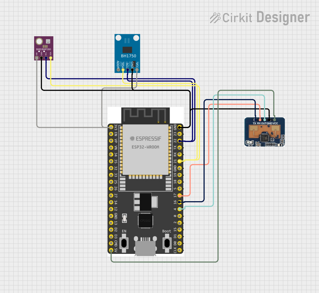
How to Use the LD2410 in a Circuit

  1. Power Supply: Connect the VCC pin to a 5V DC power supply and the GND pin to the ground.
  2. Output Connection: Connect the OUT pin to a digital input pin on your microcontroller or other control circuitry.
  3. Mounting: Place the sensor module in a location where it can effectively cover the desired detection area. Ensure there are no large metallic objects obstructing the sensor's field of view.

Important Considerations and Best Practices

  • Avoid Interference: Keep the sensor away from other high-frequency devices to avoid interference.
  • Stable Power Supply: Ensure a stable 5V power supply to avoid false triggering.
  • Environmental Factors: Be mindful of environmental factors such as temperature and humidity, which can affect sensor performance.
  • Testing: Test the sensor in the actual environment where it will be used to ensure optimal performance.

Example Code for Arduino UNO

Below is an example code to interface the LD2410 with an Arduino UNO:

// Define the pin connected to the LD2410 OUT pin
const int sensorPin = 2; // Digital pin 2

void setup() {
  // Initialize the serial communication
  Serial.begin(9600);
  
  // Set the sensor pin as input
  pinMode(sensorPin, INPUT);
}

void loop() {
  // Read the sensor output
  int sensorValue = digitalRead(sensorPin);
  
  // Check if motion is detected
  if (sensorValue == HIGH) {
    Serial.println("Motion Detected!");
  } else {
    Serial.println("No Motion");
  }
  
  // Small delay to avoid flooding the serial monitor
  delay(500);
}

Troubleshooting and FAQs

Common Issues and Solutions

  1. False Triggers:

    • Solution: Ensure a stable power supply and avoid placing the sensor near other high-frequency devices.
  2. No Detection:

    • Solution: Check the connections and ensure the sensor is powered correctly. Verify that the detection range and angle are appropriate for your application.
  3. Intermittent Detection:

    • Solution: Ensure there are no obstructions in the sensor's field of view and that it is mounted securely.

FAQs

Q1: Can the LD2410 detect motion through walls?

  • A1: The LD2410 can detect motion through non-metallic materials such as wood, plastic, and glass. However, its effectiveness may vary depending on the thickness and type of material.

Q2: What is the maximum detection range of the LD2410?

  • A2: The LD2410 can detect motion up to 10 meters away.

Q3: Can I use the LD2410 outdoors?

  • A3: Yes, the LD2410 can be used outdoors, but it should be protected from direct exposure to harsh environmental conditions.

Q4: How do I adjust the detection range and sensitivity?

  • A4: The detection range and sensitivity are typically preset. For specific adjustments, refer to the manufacturer's guidelines or use additional circuitry to fine-tune the sensor's performance.

By following this documentation, users can effectively integrate the LD2410 microwave radar sensor module into their projects, ensuring reliable motion detection and presence sensing.