How to Use Voltage Meter Sensor DC0-25 V: Examples, Pinouts, and Specs
Introduction
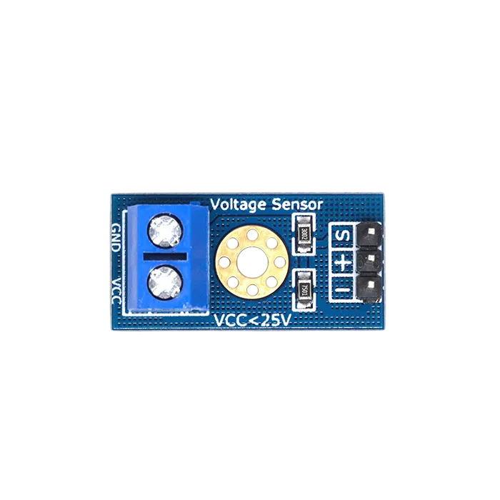
The Voltage Meter Sensor DC0-25 V is a device designed to measure the voltage in a circuit, specifically for DC voltages ranging from 0 to 25 volts. It provides accurate and reliable readings, making it an essential tool for monitoring and testing in various electronic applications. This sensor is commonly used in battery monitoring systems, power supply testing, and other projects requiring precise voltage measurement.
Explore Projects Built with Voltage Meter Sensor DC0-25 V


Explore Projects Built with Voltage Meter Sensor DC0-25 V
Technical Specifications
- Voltage Range: 0 to 25 V DC
- Input Impedance: High (to minimize circuit loading)
- Output Signal: Analog voltage proportional to the input voltage
- Accuracy: ±1% (typical)
- Operating Voltage: 3.3 V or 5 V (depending on the microcontroller used)
- Dimensions: Compact and lightweight for easy integration
- Compatibility: Works with microcontrollers like Arduino, ESP32, and Raspberry Pi
Pin Configuration and Descriptions
| Pin Name | Description |
|---|---|
VCC |
Power supply input (3.3 V or 5 V, depending on the microcontroller used). |
GND |
Ground connection. |
OUT |
Analog output signal proportional to the measured voltage. |
VIN+ |
Positive terminal for the voltage to be measured. |
VIN- |
Negative terminal for the voltage to be measured (usually connected to ground). |
Usage Instructions
How to Use the Component in a Circuit
Power the Sensor:
Connect theVCCpin to the 3.3 V or 5 V power supply of your microcontroller. Connect theGNDpin to the ground of the same power supply.Connect the Voltage Source:
Attach the voltage source to be measured across theVIN+andVIN-pins. Ensure the voltage does not exceed 25 V DC to avoid damaging the sensor.Read the Output:
TheOUTpin provides an analog voltage proportional to the input voltage. This can be read using the analog input pin of a microcontroller.Calculate the Voltage:
The output voltage is scaled down by a voltage divider circuit inside the sensor. Use the following formula to calculate the actual input voltage:
[ V_{in} = V_{out} \times \text{Scaling Factor} ]
The scaling factor is typically 5 (check the sensor's datasheet for confirmation).
Important Considerations and Best Practices
- Voltage Limits: Ensure the input voltage does not exceed 25 V DC to prevent damage.
- Analog-to-Digital Conversion: When using a microcontroller, ensure the ADC resolution is sufficient for your application. For example, a 10-bit ADC on an Arduino UNO provides 1024 levels of resolution.
- Calibration: For precise measurements, calibrate the sensor using a known voltage source.
- Noise Reduction: Use decoupling capacitors if the output signal is noisy.
Example: Using with Arduino UNO
Below is an example of how to use the Voltage Meter Sensor DC0-25 V with an Arduino UNO:
// Define the analog pin connected to the sensor's OUT pin
const int sensorPin = A0;

// Define the scaling factor (adjust based on your sensor's datasheet)
const float scalingFactor = 5.0;

void setup() {
  Serial.begin(9600); // Initialize serial communication at 9600 baud
}

void loop() {
  int sensorValue = analogRead(sensorPin); // Read the analog value from the sensor

  // Convert the analog value to voltage (assuming 5V reference and 10-bit ADC)
  float voltageOut = (sensorValue * 5.0) / 1023.0;

  // Calculate the input voltage using the scaling factor
  float voltageIn = voltageOut * scalingFactor;

  // Print the measured voltage to the Serial Monitor
  Serial.print("Measured Voltage: ");
  Serial.print(voltageIn);
  Serial.println(" V");

  delay(1000); // Wait for 1 second before the next reading
}
Troubleshooting and FAQs
Common Issues and Solutions
No Output Signal:
- Cause: Incorrect wiring or insufficient power supply.
- Solution: Double-check all connections and ensure the
VCCpin is receiving the correct voltage.
Inaccurate Readings:
- Cause: Calibration error or noise in the circuit.
- Solution: Calibrate the sensor using a known voltage source and add decoupling capacitors to reduce noise.
Output Voltage Exceeds Expected Range:
- Cause: Input voltage exceeds 25 V DC.
- Solution: Ensure the input voltage is within the specified range.
Microcontroller Not Detecting Output:
- Cause: Incorrect analog pin configuration or damaged sensor.
- Solution: Verify the analog pin setup in the code and test the sensor with a multimeter.
FAQs
Q: Can this sensor measure AC voltage?
A: No, this sensor is designed for DC voltage measurement only.Q: What is the maximum voltage the sensor can handle?
A: The sensor can measure up to 25 V DC. Exceeding this limit may damage the sensor.Q: Can I use this sensor with a 3.3 V microcontroller?
A: Yes, the sensor is compatible with both 3.3 V and 5 V systems. Ensure theVCCpin is connected to the appropriate voltage.Q: How do I improve measurement accuracy?
A: Calibrate the sensor using a precise voltage source and minimize noise in the circuit by using proper grounding and decoupling capacitors.