How to Use 4N25: Examples, Pinouts, and Specs
Introduction
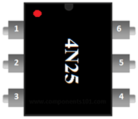
The 4N25 is an optocoupler, also known as an optoisolator, designed to transfer electrical signals between two isolated circuits using light. It typically consists of an LED and a phototransistor in a single package, providing electrical isolation and protection from high voltages. This component is widely used in applications where signal isolation is crucial, such as in power supply circuits, microcontroller interfaces, and communication systems.
Explore Projects Built with 4N25


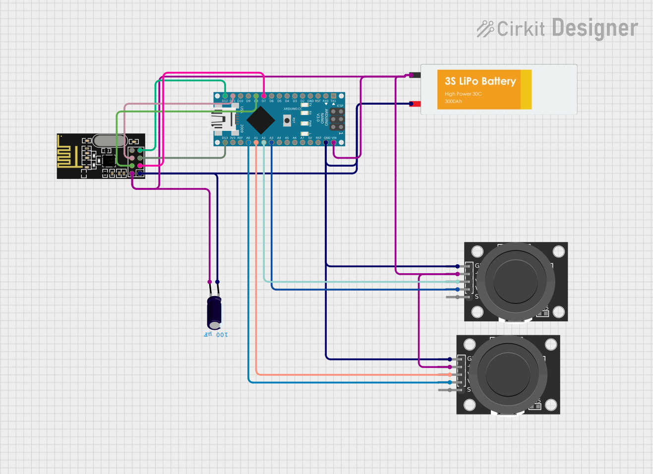
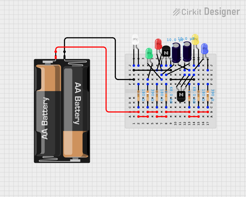
Explore Projects Built with 4N25
Technical Specifications
Key Technical Details
| Parameter | Value |
|---|---|
| LED Forward Voltage | 1.2V (typical) |
| LED Forward Current | 10mA (typical), 60mA (max) |
| Collector-Emitter Voltage (Vce) | 30V (max) |
| Collector Current (Ic) | 50mA (max) |
| Isolation Voltage | 5000V RMS |
| Current Transfer Ratio (CTR) | 20% to 300% |
| Operating Temperature Range | -55°C to +100°C |
Pin Configuration and Descriptions
| Pin Number | Name | Description |
|---|---|---|
| 1 | Anode | LED Anode (positive terminal) |
| 2 | Cathode | LED Cathode (negative terminal) |
| 3 | NC | No Connection |
| 4 | Emitter | Phototransistor Emitter |
| 5 | Collector | Phototransistor Collector |
| 6 | Base | Phototransistor Base (usually left unconnected) |
Usage Instructions
How to Use the 4N25 in a Circuit
LED Side (Input):
- Connect the anode (Pin 1) to the positive side of the input signal.
- Connect the cathode (Pin 2) to the ground or negative side of the input signal.
- Use a current-limiting resistor in series with the LED to prevent excessive current. Calculate the resistor value using Ohm's Law: ( R = \frac{V_{in} - V_f}{I_f} ), where ( V_{in} ) is the input voltage, ( V_f ) is the forward voltage of the LED, and ( I_f ) is the desired forward current.
Phototransistor Side (Output):
- Connect the collector (Pin 5) to the positive side of the output circuit.
- Connect the emitter (Pin 4) to the ground or negative side of the output circuit.
- The base (Pin 6) is typically left unconnected, but it can be used for additional control if needed.
Important Considerations and Best Practices
- Ensure the input current does not exceed the maximum rating of 60mA to avoid damaging the LED.
- Maintain proper isolation between the input and output circuits to ensure safety and prevent electrical interference.
- Use appropriate current-limiting resistors to protect the LED and phototransistor.
- Consider the current transfer ratio (CTR) when designing the circuit to ensure the output signal is sufficient for your application.
Example Circuit with Arduino UNO
Here is an example of how to connect the 4N25 optocoupler to an Arduino UNO to isolate a digital input signal:
Circuit Diagram
Arduino UNO          4N25
-----------          -----
  D2 --------------> Anode (Pin 1)
  GND --------------> Cathode (Pin 2)
  5V --------------> Collector (Pin 5)
  GND --------------> Emitter (Pin 4)
Arduino Code
// Define the input pin for the optocoupler
const int optoInputPin = 2;

// Define the output pin for the LED
const int ledPin = 13;

void setup() {
  // Initialize the input pin as an input
  pinMode(optoInputPin, INPUT);

  // Initialize the output pin as an output
  pinMode(ledPin, OUTPUT);

  // Start serial communication for debugging
  Serial.begin(9600);
}

void loop() {
  // Read the state of the optocoupler input
  int optoState = digitalRead(optoInputPin);

  // Print the state to the serial monitor
  Serial.println(optoState);

  // Control the LED based on the optocoupler input state
  if (optoState == HIGH) {
    digitalWrite(ledPin, HIGH); // Turn on the LED
  } else {
    digitalWrite(ledPin, LOW);  // Turn off the LED
  }

  // Add a small delay to avoid rapid state changes
  delay(100);
}
Troubleshooting and FAQs
Common Issues
LED Not Lighting Up:
- Check the input connections and ensure the current-limiting resistor is correctly calculated and connected.
- Verify the input voltage is sufficient to forward bias the LED.
No Output Signal:
- Ensure the phototransistor side is correctly connected to the output circuit.
- Check if the input signal is properly driving the LED.
Intermittent Operation:
- Verify all connections are secure and there are no loose wires.
- Ensure the input signal is stable and within the specified range.
Solutions and Tips for Troubleshooting
- Check Connections: Double-check all connections to ensure they are correct and secure.
- Measure Voltages: Use a multimeter to measure voltages at various points in the circuit to identify any issues.
- Verify Resistor Values: Ensure the current-limiting resistor values are appropriate for the input voltage and desired current.
- Test Components: Test the 4N25 optocoupler and other components individually to ensure they are functioning correctly.
By following this documentation, you should be able to effectively use the 4N25 optocoupler in your electronic projects, ensuring proper signal isolation and protection.