How to Use PZEM-017: Examples, Pinouts, and Specs

Introduction
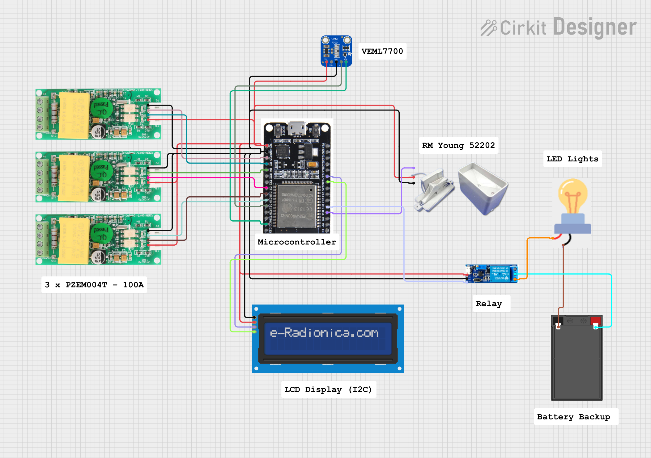
The PZEM-017 is a multifunctional energy meter manufactured by Pacefair (Part ID: 017). It is designed to measure key electrical parameters in AC circuits, including voltage, current, power, energy, and frequency. The device features a digital display for real-time monitoring and supports UART communication for seamless integration with microcontrollers and other systems.
Explore Projects Built with PZEM-017


Explore Projects Built with PZEM-017
Common Applications
- Energy monitoring in residential, commercial, and industrial environments.
- Power consumption analysis for appliances and machinery.
- Smart energy management systems for IoT applications.
- Data logging for energy usage over time.
Technical Specifications
The following table outlines the key technical details of the PZEM-017:
| Parameter | Specification |
|---|---|
| Voltage Range | 80V - 260V AC |
| Current Range | 0A - 100A (requires external CT) |
| Power Range | 0W - 22kW |
| Energy Range | 0kWh - 9999kWh |
| Frequency Range | 45Hz - 65Hz |
| Communication Interface | UART (9600 baud rate, 8N1 format) |
| Power Supply | 5V DC (external power required) |
| Accuracy | ±0.5% (under standard conditions) |
| Operating Temperature | -10°C to 60°C |
| Dimensions | 79mm x 43mm x 25mm |
Pin Configuration
The PZEM-017 has a 4-pin interface for power and communication. The pinout is as follows:
| Pin | Name | Description |
|---|---|---|
| 1 | VCC | 5V DC power supply input |
| 2 | GND | Ground connection |
| 3 | TXD | UART Transmit (connect to RX of microcontroller) |
| 4 | RXD | UART Receive (connect to TX of microcontroller) |
Usage Instructions
Connecting the PZEM-017
- Power Supply: Connect the VCC pin to a 5V DC power source and the GND pin to ground.
- UART Communication:
- Connect the TXD pin of the PZEM-017 to the RX pin of your microcontroller.
- Connect the RXD pin of the PZEM-017 to the TX pin of your microcontroller.
- Current Transformer (CT):
- Attach the external CT to the PZEM-017 and ensure it is clamped around the live wire of the AC circuit.
- Ensure the CT is oriented correctly for accurate current measurement.
- Load Connection: Connect the AC load to the circuit being monitored.
Important Considerations
- External Power: The PZEM-017 requires an external 5V DC power supply to operate.
- CT Placement: Ensure the current transformer is securely clamped around the live wire only. Do not clamp it around both live and neutral wires, as this will result in incorrect readings.
- UART Settings: Configure the UART interface of your microcontroller to 9600 baud rate, 8 data bits, no parity, and 1 stop bit (8N1 format).
- Isolation: For safety, ensure proper electrical isolation between the PZEM-017 and high-voltage AC circuits.
Example Code for Arduino UNO
Below is an example Arduino sketch to interface the PZEM-017 with an Arduino UNO:
#include <SoftwareSerial.h>

// Define RX and TX pins for SoftwareSerial
SoftwareSerial pzemSerial(10, 11); // RX = Pin 10, TX = Pin 11

void setup() {
  Serial.begin(9600); // Initialize Serial Monitor
  pzemSerial.begin(9600); // Initialize UART communication with PZEM-017

  Serial.println("PZEM-017 Energy Meter Example");
}

void loop() {
  // Send a command to request data from the PZEM-017
  byte request[] = {0x01, 0x04, 0x00, 0x00, 0x00, 0x0A, 0x70, 0x0D};
  pzemSerial.write(request, sizeof(request));

  delay(100); // Wait for the response

  // Read the response from the PZEM-017
  byte response[25];
  int index = 0;
  while (pzemSerial.available() > 0) {
    response[index++] = pzemSerial.read();
    if (index >= 25) break; // Prevent buffer overflow
  }

  // Check if a valid response is received
  if (index > 0) {
    Serial.print("Received Data: ");
    for (int i = 0; i < index; i++) {
      Serial.print(response[i], HEX);
      Serial.print(" ");
    }
    Serial.println();
  } else {
    Serial.println("No response from PZEM-017");
  }

  delay(1000); // Wait 1 second before the next request
}
Notes on the Code
- The example uses the
SoftwareSeriallibrary to communicate with the PZEM-017. Ensure the RX and TX pins are correctly connected. - The command sent in the
requestarray is a Modbus RTU query to read data from the PZEM-017. Modify this command as needed for specific data requests.
Troubleshooting and FAQs
Common Issues
No Data Received
- Cause: Incorrect UART connection or baud rate mismatch.
- Solution: Verify the TX and RX connections and ensure the baud rate is set to 9600.
Incorrect Readings
- Cause: Improper CT placement or orientation.
- Solution: Ensure the CT is clamped around the live wire only and is oriented correctly.
Device Not Powering On
- Cause: Insufficient or no power supply.
- Solution: Check the 5V DC power source and connections to the VCC and GND pins.
Intermittent Communication
- Cause: Electrical noise or loose connections.
- Solution: Use shielded cables for UART communication and ensure all connections are secure.
FAQs
Q: Can the PZEM-017 measure DC circuits?
A: No, the PZEM-017 is designed specifically for AC circuits and cannot measure DC parameters.
Q: What is the maximum current the PZEM-017 can measure?
A: The PZEM-017 can measure up to 100A using an external current transformer (CT).
Q: Can I use the PZEM-017 with a Raspberry Pi?
A: Yes, the PZEM-017 can be interfaced with a Raspberry Pi using its UART interface. Ensure proper voltage level shifting if required.
Q: How do I reset the energy reading to zero?
A: The energy reading can be reset by sending a specific Modbus RTU command to the PZEM-017. Refer to the manufacturer's protocol documentation for details.