
How to Use MQ131: Examples, Pinouts, and Specs
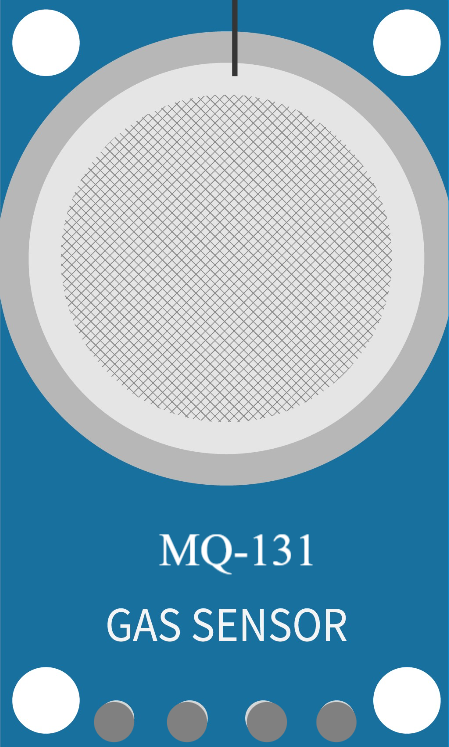
 Design with MQ131 in Cirkit Designer
Introduction
The MQ131 is a gas sensor designed to detect ozone (O₃) concentrations in the air. It operates on the principle of resistive change, where the sensor's resistance varies based on the presence of ozone. This analog output can be processed to determine ozone levels, making the MQ131 an essential component in air quality monitoring systems.
Explore Projects Built with MQ131
 Open Project in Cirkit Designer
 Open Project in Cirkit Designer
 Open Project in Cirkit Designer
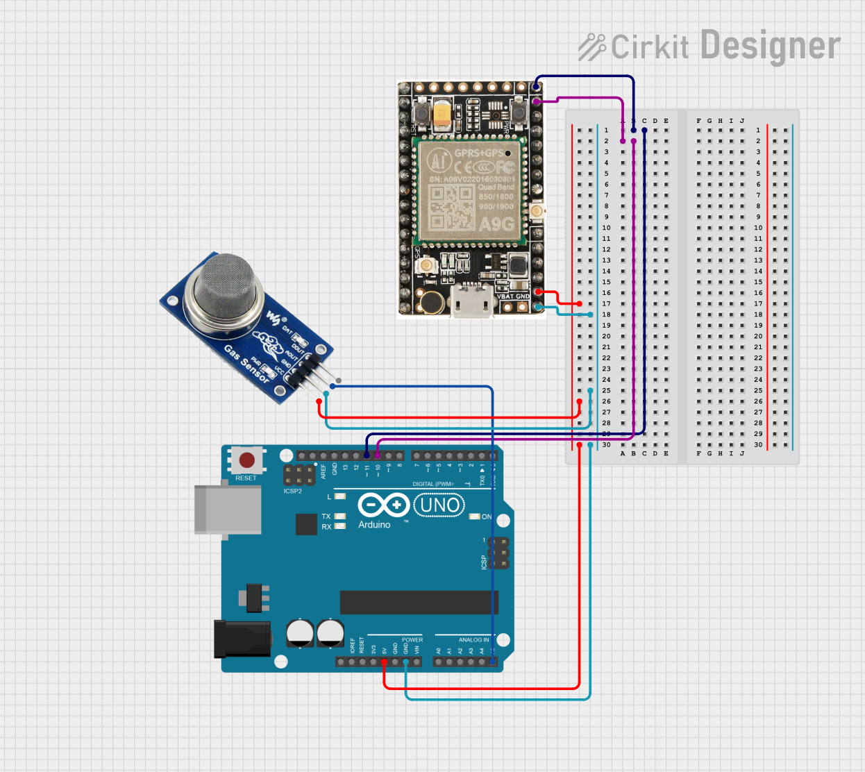 Open Project in Cirkit Designer
Explore Projects Built with MQ131
Open Project in Cirkit DesignerOpen Project in Cirkit DesignerOpen Project in Cirkit DesignerOpen Project in Cirkit DesignerCommon Applications and Use Cases
- Air quality monitoring in industrial and urban environments
- Ozone detection in laboratories and research facilities
- Environmental monitoring systems
- HVAC systems for indoor air quality control
- Ozone leak detection in sterilization equipment
Technical Specifications
The MQ131 sensor is available in two variants: low concentration and high concentration. Below are the key technical details for both variants:
| Parameter | Low Concentration Variant | High Concentration Variant |
|---|---|---|
| Detection Range | 10 ppb to 2 ppm | 1 ppm to 10 ppm |
| Heater Voltage (VH) | 5V ± 0.2V | 5V ± 0.2V |
| Load Resistance (RL) | Adjustable (10 kΩ to 47 kΩ) | Adjustable (10 kΩ to 47 kΩ) |
| Heating Current (IH) | < 120 mA | < 120 mA |
| Preheat Time | ≥ 24 hours | ≥ 24 hours |
| Operating Temperature Range | -20°C to 50°C | -20°C to 50°C |
| Humidity Range | 20% to 90% RH | 20% to 90% RH |
| Output Signal | Analog voltage | Analog voltage |
Pin Configuration and Descriptions
The MQ131 sensor module typically has 4 pins. Below is the pin configuration:
| Pin | Name | Description |
|---|---|---|
| 1 | VCC | Power supply pin. Connect to a 5V DC source. |
| 2 | GND | Ground pin. Connect to the ground of the circuit. |
| 3 | AOUT | Analog output pin. Provides a voltage proportional to the ozone concentration. |
| 4 | DOUT | Digital output pin. Outputs HIGH or LOW based on a preset threshold. |
Usage Instructions
How to Use the MQ131 in a Circuit
- Power the Sensor: Connect the VCC pin to a 5V DC power supply and the GND pin to the ground.
- Connect the Output:
- For analog readings, connect the AOUT pin to an analog input pin of your microcontroller.
- For digital readings, connect the DOUT pin to a digital input pin. Adjust the onboard potentiometer to set the threshold for the digital output.
- Preheat the Sensor: Allow the sensor to preheat for at least 24 hours before taking accurate measurements.
- Read the Output:
- Use the analog output to measure ozone concentration in real-time.
- Use the digital output for simple HIGH/LOW ozone detection based on the threshold.
Important Considerations and Best Practices
- Preheating: The MQ131 requires a long preheating time (≥ 24 hours) for stable and accurate readings.
- Calibration: Calibrate the sensor in a controlled environment with known ozone concentrations for precise measurements.
- Ventilation: Ensure proper ventilation around the sensor to avoid saturation or delayed response.
- Load Resistance: Adjust the load resistance (RL) to optimize the sensor's sensitivity and response time.
- Environmental Factors: Avoid exposing the sensor to high humidity or temperatures outside its operating range, as this may affect its performance.
Example Code for Arduino UNO
Below is an example of how to interface the MQ131 with an Arduino UNO to read analog ozone concentration values:
// Define the analog pin connected to the MQ131 AOUT pin
const int mq131Pin = A0;

void setup() {
  Serial.begin(9600); // Initialize serial communication at 9600 baud
  Serial.println("MQ131 Ozone Sensor Test");
}

void loop() {
  int sensorValue = analogRead(mq131Pin); // Read the analog value from the sensor
  float voltage = sensorValue * (5.0 / 1023.0); // Convert the analog value to voltage

  // Print the raw sensor value and voltage to the Serial Monitor
  Serial.print("Sensor Value: ");
  Serial.print(sensorValue);
  Serial.print(" | Voltage: ");
  Serial.print(voltage);
  Serial.println(" V");

  delay(1000); // Wait for 1 second before the next reading
}
Troubleshooting and FAQs
Common Issues and Solutions
No Output or Unstable Readings:
- Ensure the sensor is properly powered (5V DC) and connected to the circuit.
- Verify that the sensor has been preheated for at least 24 hours.
- Check for loose connections or damaged wires.
Inaccurate Measurements:
- Calibrate the sensor using a known ozone concentration.
- Ensure the load resistance (RL) is set correctly for your application.
- Avoid using the sensor in environments with high humidity or extreme temperatures.
Digital Output Always HIGH or LOW:
- Adjust the potentiometer on the sensor module to set an appropriate threshold.
- Verify that the ozone concentration is within the sensor's detection range.
FAQs
Q: Can the MQ131 detect gases other than ozone?
A: While the MQ131 is optimized for ozone detection, it may respond to other oxidizing gases. However, its sensitivity and accuracy for non-ozone gases are not guaranteed.
Q: How long does the sensor last?
A: The MQ131 has a typical lifespan of 2-3 years under normal operating conditions. Prolonged exposure to extreme environments may reduce its lifespan.
Q: Can I use the MQ131 with a 3.3V microcontroller?
A: The MQ131 requires a 5V power supply for the heater. However, you can use a voltage divider or level shifter to interface its output with a 3.3V microcontroller.
Q: How do I clean the sensor?
A: Avoid cleaning the sensor with liquids or solvents. If necessary, gently blow away dust or debris using compressed air.
By following this documentation, you can effectively integrate the MQ131 ozone sensor into your projects and ensure reliable performance.