How to Use SSR - 40da pequeño: Examples, Pinouts, and Specs
Introduction
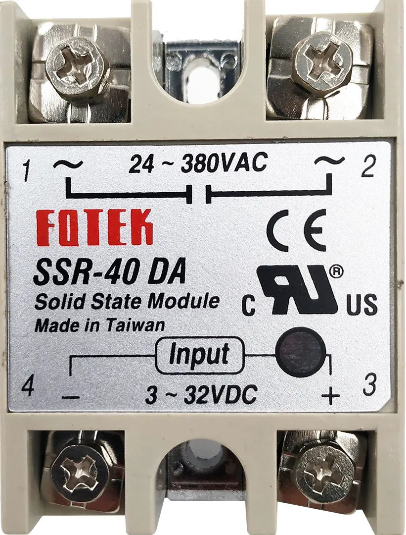
The SSR - 40DA Pequeño is a compact solid-state relay (SSR) designed for switching electrical loads without the use of mechanical components. Unlike traditional electromechanical relays, the SSR - 40DA offers faster operation, silent switching, and a significantly longer lifespan due to the absence of moving parts. This makes it ideal for applications requiring high reliability and frequent switching.
Explore Projects Built with SSR - 40da pequeño


Explore Projects Built with SSR - 40da pequeño
Common Applications and Use Cases
- Industrial automation systems
- Temperature control systems (e.g., heaters, ovens)
- Motor control and lighting systems
- Home automation projects
- Applications requiring noise-free and spark-free switching
Technical Specifications
Key Technical Details
- Input Voltage (Control Side): 3-32V DC
- Output Voltage (Load Side): 24-380V AC
- Maximum Load Current: 40A
- Trigger Current: ≤7.5mA
- Switching Speed: ≤10ms
- Dielectric Strength: ≥2500V AC
- Insulation Resistance: ≥1000MΩ at 500V DC
- Operating Temperature Range: -30°C to +80°C
- Mounting Type: Panel mount
- Dimensions: 58mm x 45mm x 23mm
Pin Configuration and Descriptions
The SSR - 40DA Pequeño has four terminals, divided into two sections: the input (control) side and the output (load) side.
| Pin Number | Label | Description |
|---|---|---|
| 1 | + (Input) | Positive terminal for the DC control signal (3-32V DC). |
| 2 | - (Input) | Negative terminal for the DC control signal (ground). |
| 3 | AC Load (1) | One terminal of the AC load to be switched. |
| 4 | AC Load (2) | The other terminal of the AC load to be switched. |
Usage Instructions
How to Use the SSR - 40DA Pequeño in a Circuit
Connect the Control Side:
- Connect the positive terminal of the DC control signal (e.g., from a microcontroller or power supply) to the
+pin. - Connect the negative terminal of the DC control signal to the
-pin. - Ensure the control voltage is within the range of 3-32V DC.
- Connect the positive terminal of the DC control signal (e.g., from a microcontroller or power supply) to the
Connect the Load Side:
- Connect one terminal of the AC load to the
AC Load (1)pin. - Connect the other terminal of the AC load to the
AC Load (2)pin. - Ensure the load voltage and current do not exceed the rated 24-380V AC and 40A, respectively.
- Connect one terminal of the AC load to the
Power the Circuit:
- When the control signal is applied, the SSR will switch the AC load on.
- When the control signal is removed, the SSR will switch the AC load off.
Important Considerations and Best Practices
- Heat Dissipation: The SSR - 40DA can generate heat during operation, especially at high loads. Use a heatsink or mount the relay on a metal surface to improve heat dissipation.
- Load Type: This SSR is designed for resistive loads (e.g., heaters, incandescent lamps). For inductive loads (e.g., motors), use a snubber circuit to protect the relay.
- Isolation: Ensure proper electrical isolation between the control and load sides to prevent damage to sensitive components.
- Wiring: Use appropriately rated wires and connectors for the load current to avoid overheating or fire hazards.
Example: Connecting the SSR - 40DA to an Arduino UNO
Below is an example of how to control the SSR - 40DA using an Arduino UNO to switch an AC load.
Circuit Diagram
- Connect the
+pin of the SSR to an Arduino digital output pin (e.g., pin 9). - Connect the
-pin of the SSR to the Arduino GND. - Connect the AC load to the
AC Load (1)andAC Load (2)pins of the SSR.
Arduino Code
// Define the pin connected to the SSR control input
const int ssrPin = 9;

void setup() {
  // Set the SSR pin as an output
  pinMode(ssrPin, OUTPUT);
}

void loop() {
  // Turn the SSR (and the connected AC load) ON
  digitalWrite(ssrPin, HIGH);
  delay(5000); // Keep the load ON for 5 seconds

  // Turn the SSR (and the connected AC load) OFF
  digitalWrite(ssrPin, LOW);
  delay(5000); // Keep the load OFF for 5 seconds
}
Notes:
- Ensure the AC load is properly connected and rated for the SSR.
- Never touch the AC load terminals while the circuit is powered.
Troubleshooting and FAQs
Common Issues and Solutions
The SSR does not switch the load:
- Verify that the control voltage is within the specified range (3-32V DC).
- Check the wiring on both the control and load sides for loose or incorrect connections.
- Ensure the load voltage and current are within the SSR's rated limits.
The SSR overheats:
- Ensure proper heat dissipation by using a heatsink or mounting the SSR on a metal surface.
- Check that the load current does not exceed 40A.
The load flickers or does not stay on:
- Verify the stability of the control signal voltage.
- For inductive loads, use a snubber circuit to suppress voltage spikes.
The SSR is damaged or not functioning:
- Check for short circuits or overvoltage conditions on the load side.
- Ensure the SSR is not exposed to temperatures beyond its operating range.
FAQs
Q: Can I use the SSR - 40DA Pequeño with a DC load?
A: No, this SSR is designed specifically for AC loads. For DC loads, use a DC-specific SSR.
Q: Is the SSR - 40DA optically isolated?
A: Yes, the control and load sides are optically isolated to protect the control circuit from high voltages.
Q: Can I use the SSR with an inductive load like a motor?
A: Yes, but you must use a snubber circuit to protect the SSR from voltage spikes caused by the inductive load.
Q: What happens if I exceed the rated current or voltage?
A: Exceeding the rated limits can damage the SSR permanently. Always ensure the load is within the specified range.
Q: Does the SSR make any noise during operation?
A: No, the SSR operates silently as it has no moving parts.