Cirkit Designer
Your all-in-one circuit design IDE
Home /
Component Documentation
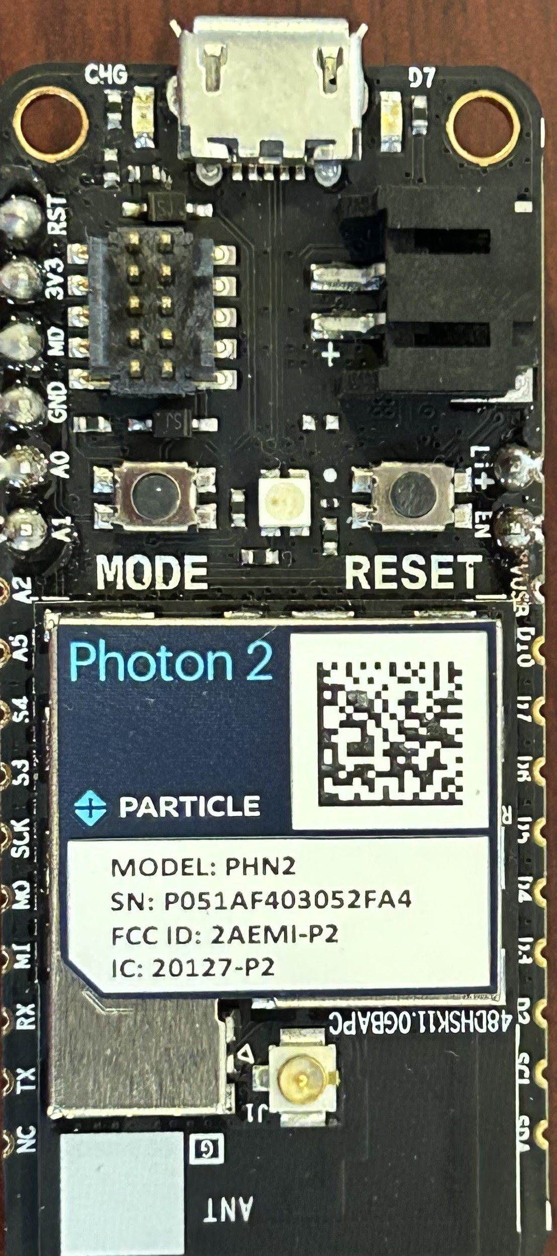
How to Use Photon P2 Microcontroller: Examples, Pinouts, and Specs
Introduction
The Photon P2 Microcontroller, manufactured by Particle, is a powerful Wi-Fi microcontroller module designed specifically for IoT (Internet of Things) applications. Featuring a dual-core ARM Cortex-M4 processor, ample memory, and extensive connectivity options, the P2 is ideal for a wide range of applications, from home automation to industrial monitoring.
Explore Projects Built with Photon P2 Microcontroller
Photon 2 Motion Detector Alarm with PIR Sensor and Wi-Fi Control
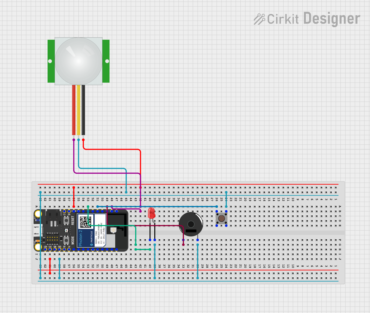
This circuit is a motion-activated alarm system using a Photon microcontroller, a PIR sensor, a piezo buzzer, a red LED, and a pushbutton. When motion is detected by the PIR sensor, the red LED lights up and the buzzer sounds an alarm, which can be deactivated manually via the pushbutton or remotely through the Particle Cloud.
Raspberry Pi Pico Controlled Robot with Ultrasonic Sensing and Light Detection
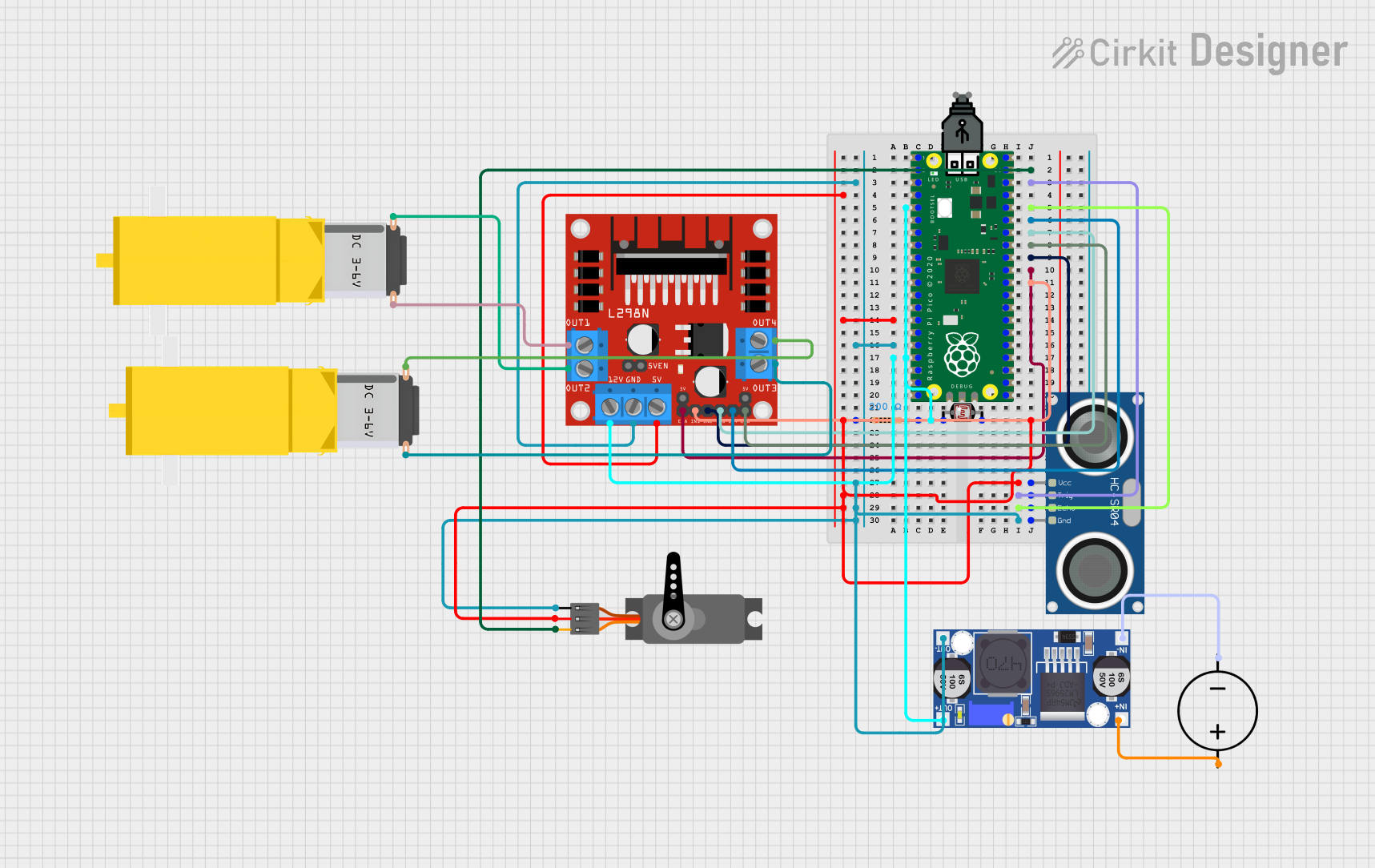
This circuit features a Raspberry Pi Pico microcontroller as the central processing unit, interfacing with a variety of components. It controls a servo motor, reads from a photocell (LDR) with a resistor forming a voltage divider, and communicates with an HC-SR04 ultrasonic sensor for distance measurement. The circuit also includes an L298N motor driver to operate two DC gearmotors, with power regulation provided by a buck converter connected to a DC power source.
Raspberry Pi Pico W-Based Smart Home Automation System with Motion Detection and Environmental Monitoring
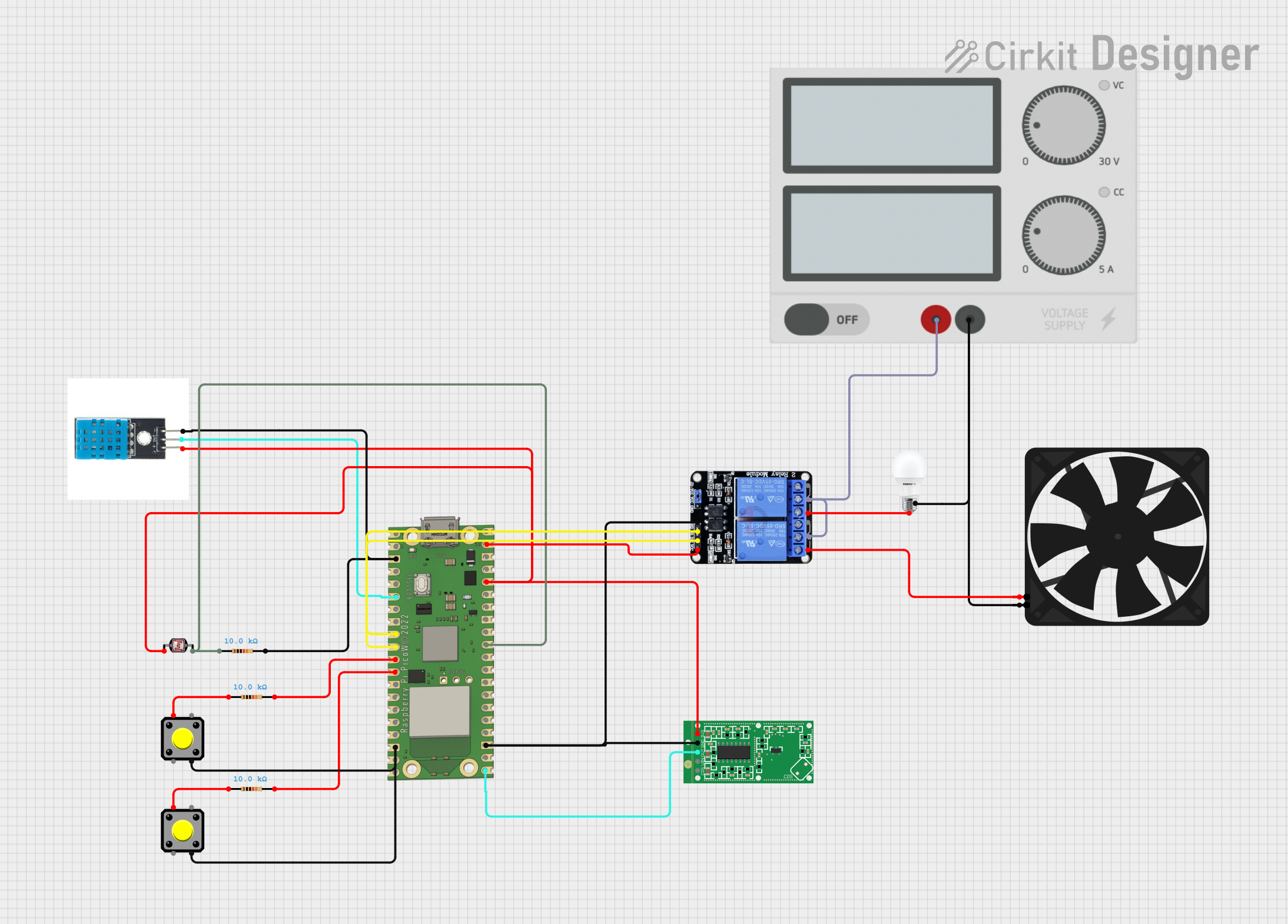
This circuit features a Raspberry Pi Pico W microcontroller connected to various sensors and actuators, including a DHT11 temperature and humidity sensor, an RCWL-0516 microwave radar motion sensor, a photocell (LDR) with a resistor for light detection, and a two-channel relay controlling a bulb and a fan. The microcontroller runs code to monitor environmental conditions and motion, displaying information on an LCD and allowing remote control via MQTT messages over Wi-Fi. It supports both automatic sensor-based operation and remote app control, with pushbuttons to switch between modes.
Raspberry Pi Pico Controlled Alternating LED Indicator
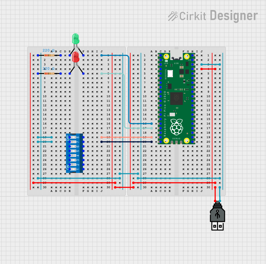
This circuit features a Raspberry Pi Pico microcontroller used to control two LEDs (one red, one green) through GPIO pins 16 and 17. The LEDs are each connected in series with a 220-ohm resistor to limit current, and the Pico is powered via a USB power connection. The embedded code alternates the LEDs on and off every second, and there are connections to a DIP switch, which suggests potential user input to modify the behavior, although the switch is not utilized in the provided code.
Explore Projects Built with Photon P2 Microcontroller
Photon 2 Motion Detector Alarm with PIR Sensor and Wi-Fi Control
This circuit is a motion-activated alarm system using a Photon microcontroller, a PIR sensor, a piezo buzzer, a red LED, and a pushbutton. When motion is detected by the PIR sensor, the red LED lights up and the buzzer sounds an alarm, which can be deactivated manually via the pushbutton or remotely through the Particle Cloud.
Raspberry Pi Pico Controlled Robot with Ultrasonic Sensing and Light Detection
This circuit features a Raspberry Pi Pico microcontroller as the central processing unit, interfacing with a variety of components. It controls a servo motor, reads from a photocell (LDR) with a resistor forming a voltage divider, and communicates with an HC-SR04 ultrasonic sensor for distance measurement. The circuit also includes an L298N motor driver to operate two DC gearmotors, with power regulation provided by a buck converter connected to a DC power source.
Raspberry Pi Pico W-Based Smart Home Automation System with Motion Detection and Environmental Monitoring
This circuit features a Raspberry Pi Pico W microcontroller connected to various sensors and actuators, including a DHT11 temperature and humidity sensor, an RCWL-0516 microwave radar motion sensor, a photocell (LDR) with a resistor for light detection, and a two-channel relay controlling a bulb and a fan. The microcontroller runs code to monitor environmental conditions and motion, displaying information on an LCD and allowing remote control via MQTT messages over Wi-Fi. It supports both automatic sensor-based operation and remote app control, with pushbuttons to switch between modes.
Raspberry Pi Pico Controlled Alternating LED Indicator
This circuit features a Raspberry Pi Pico microcontroller used to control two LEDs (one red, one green) through GPIO pins 16 and 17. The LEDs are each connected in series with a 220-ohm resistor to limit current, and the Pico is powered via a USB power connection. The embedded code alternates the LEDs on and off every second, and there are connections to a DIP switch, which suggests potential user input to modify the behavior, although the switch is not utilized in the provided code.
Common Applications and Use Cases
- Home Automation: Control and monitor home devices remotely.
- Industrial Monitoring: Collect and transmit data from industrial sensors.
- Wearable Devices: Integrate into wearable tech for health and fitness tracking.
- Smart Agriculture: Monitor and control agricultural environments.
- Environmental Monitoring: Collect data on environmental conditions like temperature and humidity.
Technical Specifications
Key Technical Details
| Specification | Value |
|---|---|
| Processor | Dual-core ARM Cortex-M4 |
| Clock Speed | 120 MHz |
| Flash Memory | 4 MB |
| RAM | 512 KB |
| Wi-Fi | 802.11 b/g/n (2.4 GHz) |
| Operating Voltage | 3.3V |
| Input Voltage Range | 3.0V to 3.6V |
| Digital I/O Pins | 24 |
| Analog Input Pins | 8 |
| UART | 2 |
| SPI | 2 |
| I2C | 2 |
| Power Consumption | 80 mA (typical) |
| Dimensions | 20 mm x 30 mm |
Pin Configuration and Descriptions
| Pin Number | Pin Name | Description |
|---|---|---|
| 1 | GND | Ground |
| 2 | 3V3 | 3.3V Power Supply |
| 3 | D0 | Digital I/O |
| 4 | D1 | Digital I/O |
| 5 | D2 | Digital I/O |
| 6 | D3 | Digital I/O |
| 7 | D4 | Digital I/O |
| 8 | D5 | Digital I/O |
| 9 | D6 | Digital I/O |
| 10 | D7 | Digital I/O |
| 11 | A0 | Analog Input |
| 12 | A1 | Analog Input |
| 13 | A2 | Analog Input |
| 14 | A3 | Analog Input |
| 15 | A4 | Analog Input |
| 16 | A5 | Analog Input |
| 17 | TX | UART Transmit |
| 18 | RX | UART Receive |
| 19 | SCL | I2C Clock |
| 20 | SDA | I2C Data |
| 21 | SPI_CLK | SPI Clock |
| 22 | SPI_MISO | SPI Master In Slave Out |
| 23 | SPI_MOSI | SPI Master Out Slave In |
| 24 | RST | Reset |
Usage Instructions
How to Use the Component in a Circuit
- Power Supply: Connect the 3V3 pin to a 3.3V power supply and the GND pin to ground.
- Digital I/O: Use the digital I/O pins (D0-D7) for interfacing with digital sensors and actuators.
- Analog Inputs: Connect analog sensors to the analog input pins (A0-A5).
- UART Communication: Use the TX and RX pins for serial communication.
- I2C Communication: Connect the SCL and SDA pins to I2C devices.
- SPI Communication: Use the SPI_CLK, SPI_MISO, and SPI_MOSI pins for SPI communication.
Important Considerations and Best Practices
- Voltage Levels: Ensure that all connected devices operate at 3.3V to avoid damaging the P2.
- Decoupling Capacitors: Use decoupling capacitors close to the power supply pins to reduce noise.
- Reset Pin: Connect a push-button to the RST pin for manual reset functionality.
- Antenna: Ensure proper antenna placement for optimal Wi-Fi performance.
Example Code for Arduino UNO
#include <Wire.h>

void setup() {
  // Initialize serial communication at 9600 baud rate
  Serial.begin(9600);

  // Initialize I2C communication
  Wire.begin();

  // Set pin modes for digital I/O
  pinMode(D0, OUTPUT);
  pinMode(D1, INPUT);
}

void loop() {
  // Read digital input from pin D1
  int sensorValue = digitalRead(D1);

  // Print the sensor value to the serial monitor
  Serial.println(sensorValue);

  // Write a HIGH signal to pin D0
  digitalWrite(D0, HIGH);

  // Wait for 1 second
  delay(1000);

  // Write a LOW signal to pin D0
  digitalWrite(D0, LOW);

  // Wait for 1 second
  delay(1000);
}
Troubleshooting and FAQs
Common Issues Users Might Face
Wi-Fi Connectivity Issues:
- Solution: Ensure the antenna is properly connected and placed. Check Wi-Fi credentials and signal strength.
Power Supply Problems:
- Solution: Verify that the power supply provides a stable 3.3V. Use decoupling capacitors to reduce noise.
Incorrect Pin Connections:
- Solution: Double-check the pin configuration and ensure all connections are correct.
Serial Communication Errors:
- Solution: Ensure the correct baud rate is set and that TX/RX pins are properly connected.
Solutions and Tips for Troubleshooting
- Check Connections: Always verify that all connections are secure and correct.
- Use a Multimeter: Measure voltage levels and continuity to diagnose electrical issues.
- Update Firmware: Ensure the P2 microcontroller firmware is up to date.
- Consult Documentation: Refer to the Particle documentation for additional support and resources.
By following this documentation, users can effectively integrate and utilize the Photon P2 Microcontroller in their IoT projects, ensuring reliable performance and connectivity.