How to Use Arduino 2650 Mega Sensor Shield: Examples, Pinouts, and Specs
Introduction
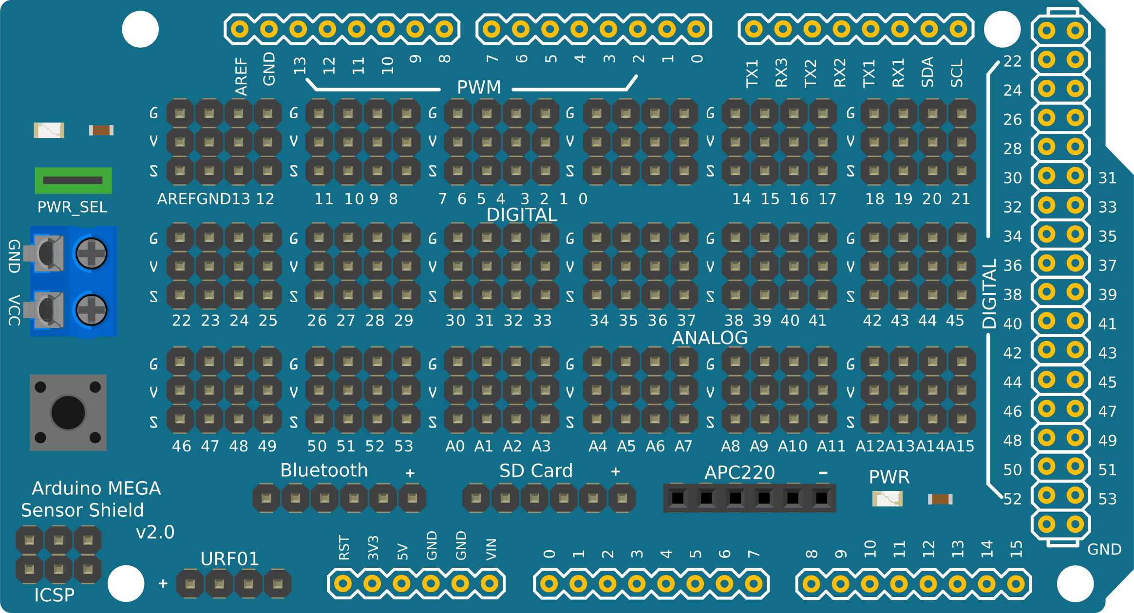
The Arduino 2650 Mega Sensor Shield is a versatile expansion board designed specifically for the Arduino Mega. It provides additional sensor connections and interfaces, making it easier to integrate various sensors, modules, and actuators into your projects. This shield simplifies wiring and enhances the functionality of the Arduino Mega by offering a wide range of input/output (I/O) ports and connectors.
Explore Projects Built with Arduino 2650 Mega Sensor Shield
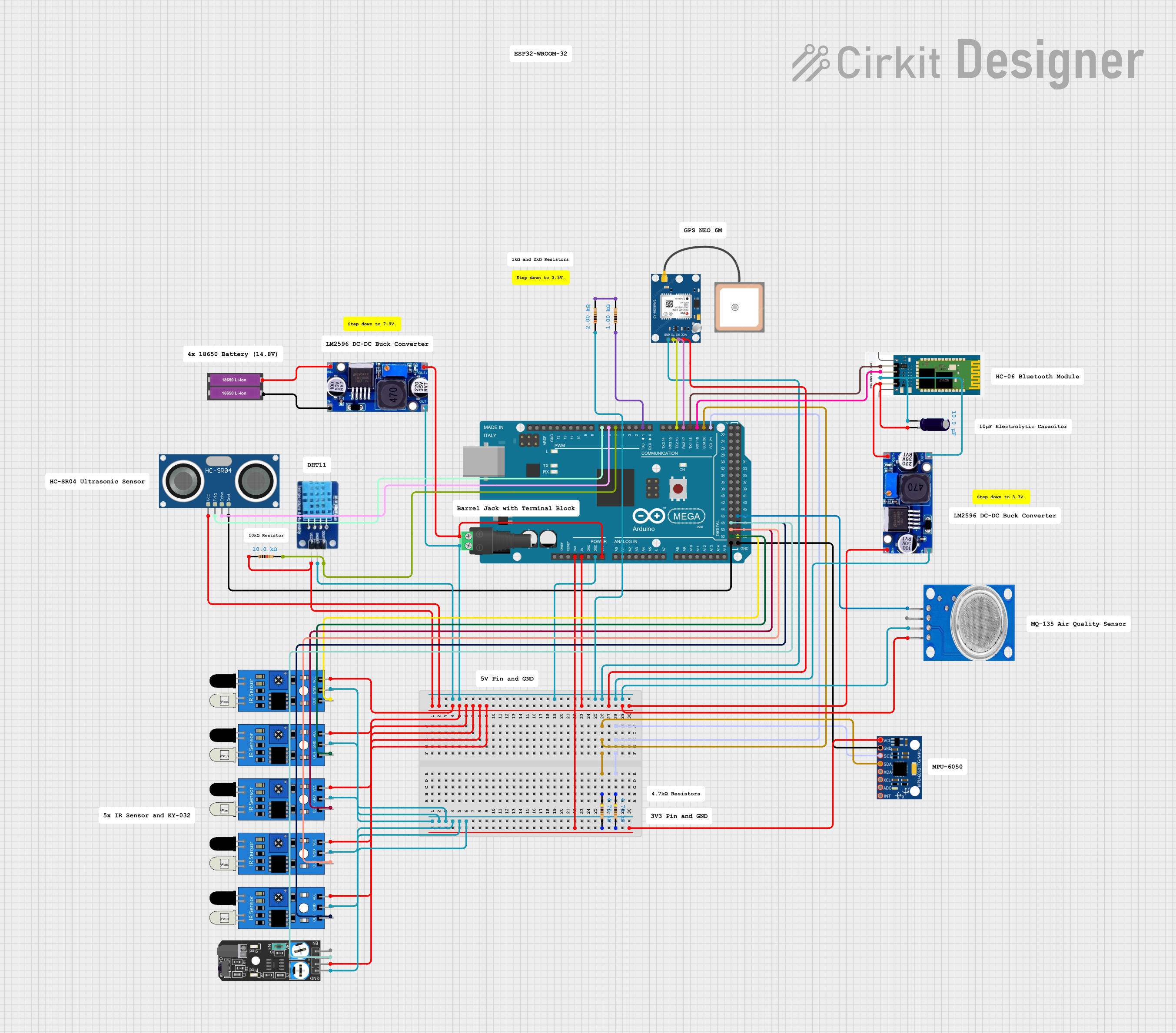
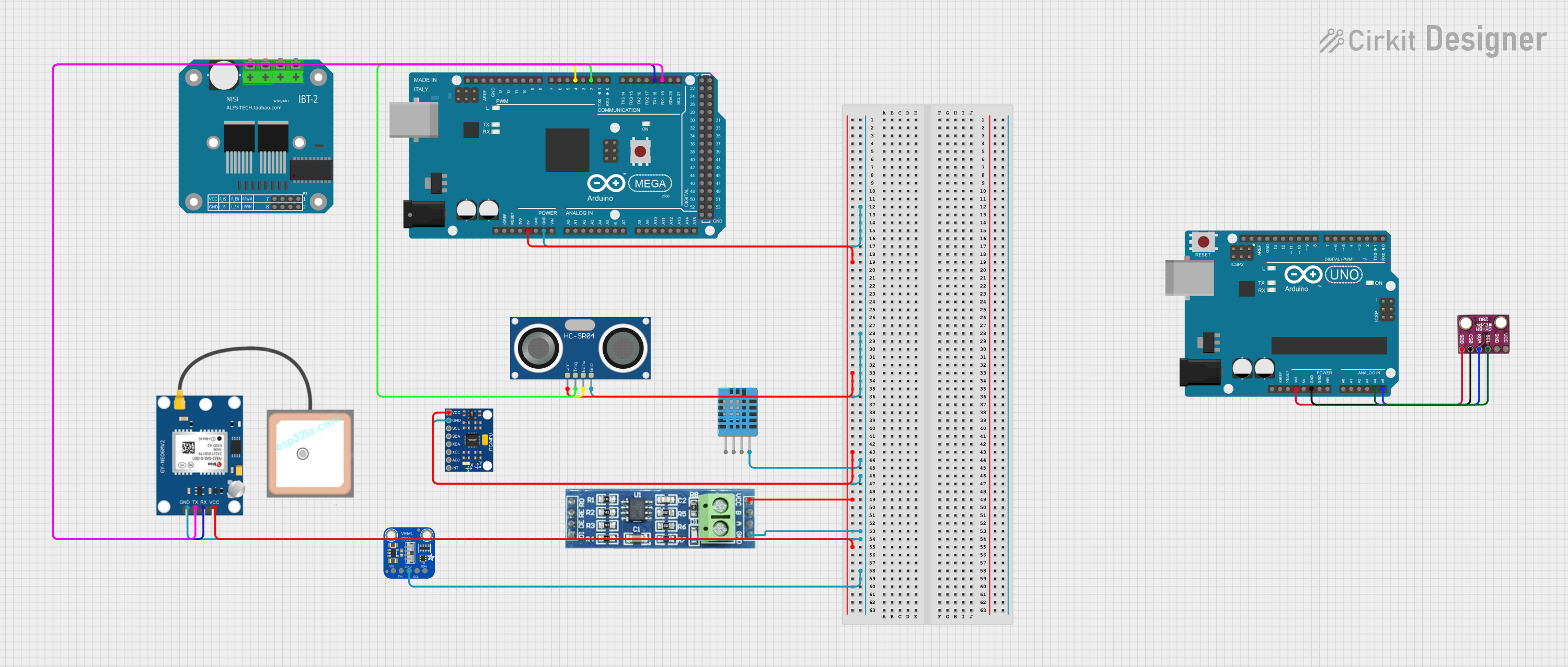

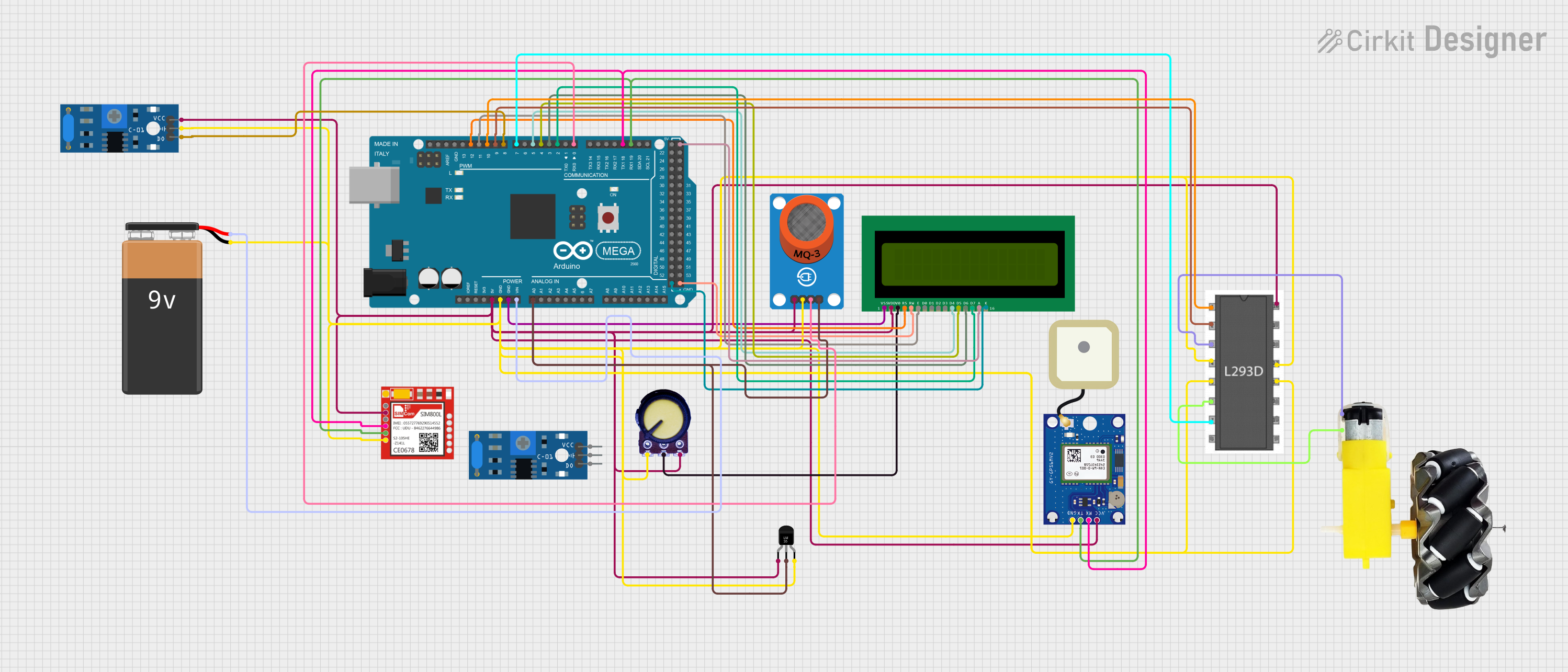
Explore Projects Built with Arduino 2650 Mega Sensor Shield
Common Applications and Use Cases
- Robotics projects requiring multiple sensors and actuators
- Home automation systems with numerous input/output devices
- IoT (Internet of Things) applications
- Prototyping and testing of sensor-based systems
- Educational projects for learning about sensors and microcontrollers
Technical Specifications
The Arduino 2650 Mega Sensor Shield is designed to expand the capabilities of the Arduino Mega. Below are its key technical details:
Key Technical Details
- Compatible Board: Arduino Mega 2560
- Operating Voltage: 5V (supplied by the Arduino Mega)
- Number of Digital I/O Pins: 54 (D0–D53)
- Number of Analog Input Pins: 16 (A0–A15)
- Communication Interfaces: UART, I2C, SPI
- Dedicated Servo Headers: 15 (with 3-pin connectors for signal, power, and ground)
- Power Supply: Supports external power input for high-power devices
- Dimensions: Matches the Arduino Mega form factor
Pin Configuration and Descriptions
The Arduino 2650 Mega Sensor Shield provides easy access to the Arduino Mega's pins through labeled connectors. Below is a breakdown of the pin configuration:
Digital I/O Pins
| Pin Number | Description |
|---|---|
| D0–D13 | General-purpose digital I/O |
| D14–D21 | UART communication (TX/RX pins) |
| D22–D53 | Additional digital I/O |
Analog Input Pins
| Pin Number | Description |
|---|---|
| A0–A15 | Analog input pins (10-bit ADC) |
Communication Interfaces
| Interface | Pins Used | Description |
|---|---|---|
| UART | D0–D3, D14–D21 | Serial communication |
| I2C | A4 (SDA), A5 (SCL) | Inter-integrated circuit communication |
| SPI | D50 (MISO), D51 (MOSI), D52 (SCK), D53 (SS) | Serial Peripheral Interface |
Servo Headers
| Header Number | Pins Provided | Description |
|---|---|---|
| 1–15 | Signal, VCC, GND | Dedicated 3-pin headers for servos |
Usage Instructions
How to Use the Arduino 2650 Mega Sensor Shield
- Attach the Shield: Align the pins of the sensor shield with the headers on the Arduino Mega and press gently to secure the connection.
- Connect Sensors and Modules: Use the labeled connectors on the shield to attach sensors, actuators, or modules. Ensure proper alignment of signal, power (VCC), and ground (GND) pins.
- Power the System: Power the Arduino Mega via USB or an external power supply. If using high-power devices, connect an external power source to the shield's power input.
- Upload Code: Write and upload your Arduino sketch using the Arduino IDE. Ensure the correct board and port are selected in the IDE.
Important Considerations and Best Practices
- Power Supply: For projects with multiple high-power devices (e.g., servos), use an external power source to avoid overloading the Arduino Mega's onboard regulator.
- Pin Conflicts: Avoid using the same pins for multiple functions. Check your code and wiring to ensure no conflicts.
- Sensor Compatibility: Verify that the sensors and modules you connect are compatible with the Arduino Mega's 5V logic level.
- Cable Management: Use short, organized cables to minimize noise and interference in your circuit.
Example Code for Arduino Mega with Sensor Shield
Below is an example of how to use the sensor shield to read data from an analog sensor (e.g., a potentiometer) and control a servo motor:
#include <Servo.h> // Include the Servo library

Servo myServo; // Create a Servo object

const int analogPin = A0; // Analog sensor connected to A0
const int servoPin = 9;   // Servo connected to digital pin 9

void setup() {
  myServo.attach(servoPin); // Attach the servo to the specified pin
  Serial.begin(9600);       // Initialize serial communication
}

void loop() {
  int sensorValue = analogRead(analogPin); // Read the analog sensor value
  int servoAngle = map(sensorValue, 0, 1023, 0, 180);
  // Map sensor value to servo angle (0-180 degrees)

  myServo.write(servoAngle); // Set the servo position
  Serial.print("Sensor Value: ");
  Serial.print(sensorValue); // Print sensor value to the Serial Monitor
  Serial.print(" | Servo Angle: ");
  Serial.println(servoAngle); // Print servo angle to the Serial Monitor

  delay(100); // Small delay for stability
}
Troubleshooting and FAQs
Common Issues and Solutions
Issue: The shield does not power up.
- Solution: Ensure the Arduino Mega is properly powered via USB or an external power supply. Check the shield's power connections.
Issue: Sensors or modules are not responding.
- Solution: Verify that the sensors/modules are connected to the correct pins. Double-check the wiring for proper alignment of signal, VCC, and GND.
Issue: Servo motors are jittering or not moving.
- Solution: Use an external power source for the shield to provide sufficient current for the servos. Ensure the servo signal pin is connected to the correct digital pin.
Issue: Serial communication is not working.
- Solution: Ensure the correct UART pins are used and that the baud rate in the code matches the Serial Monitor settings.
FAQs
Q: Can I use this shield with an Arduino Uno?
- A: No, this shield is specifically designed for the Arduino Mega due to its larger number of pins and form factor.
Q: How many servos can I control with this shield?
- A: The shield provides 15 dedicated servo headers, allowing you to control up to 15 servos.
Q: Can I use both I2C and SPI devices simultaneously?
- A: Yes, the shield supports both I2C and SPI communication. Ensure that the devices do not have conflicting addresses or pin assignments.
Q: Do I need additional libraries to use this shield?
- A: No additional libraries are required for the shield itself. However, specific sensors or modules may require their own libraries.
This concludes the documentation for the Arduino 2650 Mega Sensor Shield.