
How to Use DOSonCHIP IC: Examples, Pinouts, and Specs
 Design with DOSonCHIP IC in Cirkit Designer
Introduction
The DOSonCHIP IC (CD17B10), manufactured by Wearable Inc., is a compact integrated circuit designed for digital signal processing (DSP). It is optimized for high-speed data handling and efficient power management, making it an ideal choice for applications requiring robust performance in a small form factor. This IC is commonly used in devices such as portable electronics, IoT systems, and embedded computing platforms.
Explore Projects Built with DOSonCHIP IC
 Open Project in Cirkit Designer
 Open Project in Cirkit Designer
 Open Project in Cirkit Designer
 Open Project in Cirkit Designer
Explore Projects Built with DOSonCHIP IC
Open Project in Cirkit DesignerOpen Project in Cirkit DesignerOpen Project in Cirkit DesignerOpen Project in Cirkit DesignerCommon Applications
- High-speed data processing in IoT devices
- Signal filtering and transformation in audio systems
- Power-efficient DSP in wearable electronics
- Data compression and decompression in communication systems
- Real-time processing in robotics and automation
Technical Specifications
Key Technical Details
| Parameter | Value |
|---|---|
| Manufacturer | Wearable Inc. |
| Part Number | CD17B10 |
| Supply Voltage (Vcc) | 1.8V to 3.3V |
| Operating Current | 15 mA (typical) |
| Power Consumption | 50 mW (maximum) |
| Clock Speed | Up to 200 MHz |
| Operating Temperature | -40°C to +85°C |
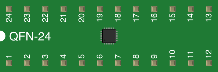
| Package Type | QFN-32 (Quad Flat No-lead) |
Pin Configuration and Descriptions
The DOSonCHIP IC features a 32-pin QFN package. Below is the pin configuration and description:
| Pin Number | Pin Name | Type | Description |
|---|---|---|---|
| 1 | VCC | Power | Positive supply voltage (1.8V to 3.3V). |
| 2 | GND | Ground | Ground connection. |
| 3 | CLK_IN | Input | External clock input (up to 200 MHz). |
| 4 | RESET | Input | Active-low reset pin. |
| 5 | DATA_IN | Input | Digital data input for processing. |
| 6 | DATA_OUT | Output | Processed digital data output. |
| 7-10 | GPIO[0-3] | I/O | General-purpose input/output pins. |
| 11 | INT | Output | Interrupt signal output. |
| 12-31 | NC | - | No connection (reserved for future use). |
| 32 | TEST | Input | Test mode activation (for debugging purposes). |
Usage Instructions
How to Use the Component in a Circuit
- Power Supply: Connect the VCC pin to a stable power source within the range of 1.8V to 3.3V. Ensure proper decoupling capacitors (e.g., 0.1 µF and 10 µF) are placed close to the VCC and GND pins to minimize noise.
- Clock Input: Provide a clock signal to the CLK_IN pin. The frequency should not exceed 200 MHz.
- Reset: Use the RESET pin to initialize the IC. Pull this pin low momentarily to reset the device.
- Data Input/Output: Feed digital signals to the DATA_IN pin for processing. The processed output will be available on the DATA_OUT pin.
- GPIO Pins: Configure the GPIO pins as needed for additional functionality, such as controlling external devices or reading sensor data.
- Interrupt Handling: Use the INT pin to monitor interrupt signals generated by the IC.
Important Considerations and Best Practices
- Thermal Management: Ensure adequate heat dissipation, especially in high-speed applications. Use a PCB with a thermal pad under the IC for optimal performance.
- Signal Integrity: Use short and properly terminated traces for high-speed signals to avoid signal degradation.
- Debugging: The TEST pin can be used for debugging purposes. Leave it unconnected in normal operation.
- Power Sequencing: Apply power to the VCC pin before providing any input signals to avoid damage to the IC.
Example: Connecting to an Arduino UNO
The DOSonCHIP IC can be interfaced with an Arduino UNO for basic DSP tasks. Below is an example of how to connect and program the IC:
Circuit Connections
- Connect the VCC pin of the IC to the 3.3V pin on the Arduino.
- Connect the GND pin of the IC to the GND pin on the Arduino.
- Connect the DATA_IN pin of the IC to Arduino digital pin 2.
- Connect the DATA_OUT pin of the IC to Arduino digital pin 3.
- Connect the RESET pin of the IC to Arduino digital pin 4.
Arduino Code Example
// Example code to interface with the DOSonCHIP IC (CD17B10)
// This code sends data to the IC and reads the processed output.

#define DATA_IN_PIN 2  // Arduino pin connected to DATA_IN
#define DATA_OUT_PIN 3 // Arduino pin connected to DATA_OUT
#define RESET_PIN 4    // Arduino pin connected to RESET

void setup() {
  pinMode(DATA_IN_PIN, OUTPUT);  // Set DATA_IN as output
  pinMode(DATA_OUT_PIN, INPUT); // Set DATA_OUT as input
  pinMode(RESET_PIN, OUTPUT);   // Set RESET as output

  // Initialize serial communication for debugging
  Serial.begin(9600);

  // Reset the DOSonCHIP IC
  digitalWrite(RESET_PIN, LOW);
  delay(10); // Hold reset low for 10ms
  digitalWrite(RESET_PIN, HIGH);
  delay(10); // Wait for the IC to initialize
}

void loop() {
  // Send a sample data byte to the IC
  digitalWrite(DATA_IN_PIN, HIGH); // Example: Sending a HIGH signal
  delay(1); // Wait for processing

  // Read the processed output from the IC
  int processedData = digitalRead(DATA_OUT_PIN);

  // Print the processed data to the serial monitor
  Serial.println(processedData);

  delay(1000); // Wait 1 second before sending the next data
}
Troubleshooting and FAQs
Common Issues and Solutions
No Output on DATA_OUT Pin
- Cause: The IC may not be properly powered or initialized.
- Solution: Verify the power supply voltage and ensure the RESET pin is toggled during startup.
High Power Consumption
- Cause: Excessive clock frequency or improper thermal management.
- Solution: Reduce the clock frequency and ensure proper heat dissipation.
Interrupt Signal Not Triggering
- Cause: Incorrect configuration of the GPIO or INT pin.
- Solution: Check the GPIO pin configuration and ensure the INT pin is connected to the appropriate circuit.
IC Overheating
- Cause: Insufficient cooling or excessive current draw.
- Solution: Use a PCB with a thermal pad and ensure the IC is not overloaded.
FAQs
Q1: Can the DOSonCHIP IC operate at 5V?
A1: No, the IC is designed to operate within a supply voltage range of 1.8V to 3.3V. Exceeding this range may damage the IC.
Q2: What is the maximum data rate supported by the IC?
A2: The maximum data rate depends on the clock frequency. At 200 MHz, the IC can handle data rates up to 100 Mbps.
Q3: Are the GPIO pins configurable as analog inputs?
A3: No, the GPIO pins are digital-only and cannot be used for analog input.
Q4: Is the IC compatible with 1.8V logic levels?
A4: Yes, the IC supports logic levels as low as 1.8V, making it compatible with low-power systems.