
How to Use PD 65W module: Examples, Pinouts, and Specs
 Design with PD 65W module in Cirkit Designer
Introduction
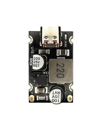
The PD 65W Module (Manufacturer: Stas, Part ID: 4) is a high-performance Power Delivery (PD) module designed to deliver up to 65 watts of power. It is primarily used in USB-C applications to provide fast and efficient charging for a wide range of devices, including laptops, smartphones, tablets, and other electronics. This module supports multiple voltage levels, making it versatile for various power delivery requirements.
Explore Projects Built with PD 65W module
 Open Project in Cirkit Designer
 Open Project in Cirkit Designer
 Open Project in Cirkit Designer
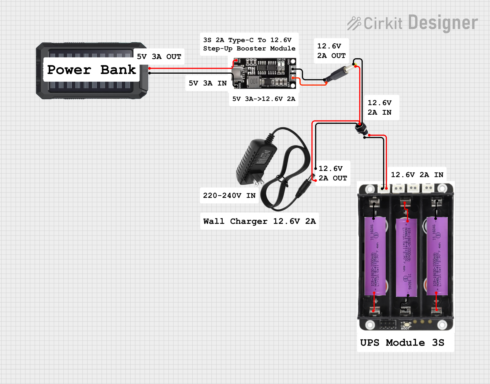 Open Project in Cirkit Designer
Explore Projects Built with PD 65W module
Open Project in Cirkit DesignerOpen Project in Cirkit DesignerOpen Project in Cirkit DesignerOpen Project in Cirkit DesignerCommon Applications
- USB-C fast charging for laptops, smartphones, and tablets
- Powering USB-C hubs and docking stations
- Integration into power adapters and chargers
- Use in embedded systems requiring USB-C PD functionality
Technical Specifications
The following table outlines the key technical specifications of the PD 65W Module:
| Parameter | Value |
|---|---|
| Input Voltage Range | 5V to 20V |
| Output Voltage Levels | 5V, 9V, 12V, 15V, 20V |
| Maximum Output Power | 65W |
| Efficiency | Up to 94% |
| Communication Protocol | USB Power Delivery (PD 3.0) |
| Operating Temperature | -20°C to 85°C |
| Dimensions | 30mm x 20mm x 10mm |
Pin Configuration and Descriptions
The PD 65W Module has the following pin configuration:
| Pin | Name | Description |
|---|---|---|
| 1 | VIN | Input voltage pin (5V to 20V). Connect to the power source. |
| 2 | GND | Ground pin. Connect to the ground of the power source. |
| 3 | VOUT | Output voltage pin. Provides regulated output voltage based on PD negotiation. |
| 4 | CC1 | USB-C Configuration Channel 1. Used for PD communication. |
| 5 | CC2 | USB-C Configuration Channel 2. Used for PD communication. |
| 6 | EN | Enable pin. Pull high to enable the module, low to disable. |
| 7 | I2C_SCL | I2C clock line for optional configuration or monitoring. |
| 8 | I2C_SDA | I2C data line for optional configuration or monitoring. |
Usage Instructions
How to Use the PD 65W Module in a Circuit
- Power Input: Connect the VIN pin to a DC power source (5V to 20V) and the GND pin to the ground of the power source.
- USB-C Connection: Connect the CC1 and CC2 pins to the corresponding Configuration Channel pins of a USB-C connector.
- Output Voltage: The VOUT pin will provide the negotiated output voltage based on the connected device's requirements.
- Enable the Module: Pull the EN pin high to activate the module. If left low, the module will remain disabled.
- Optional I2C Configuration: Use the I2C_SCL and I2C_SDA pins to configure or monitor the module via an I2C interface.
Important Considerations
- Ensure the input voltage is within the specified range (5V to 20V) to avoid damage to the module.
- Use appropriate heat dissipation methods if the module operates at high power levels for extended periods.
- When connecting to a USB-C device, ensure the CC1 and CC2 pins are properly wired to enable PD communication.
- For custom configurations, refer to the I2C protocol documentation provided by the manufacturer.
Example: Using the PD 65W Module with an Arduino UNO
The PD 65W Module can be monitored or configured using an Arduino UNO via the I2C interface. Below is an example code snippet to read data from the module:
#include <Wire.h> // Include the Wire library for I2C communication

#define PD_MODULE_I2C_ADDRESS 0x28 // Replace with the actual I2C address of the module

void setup() {
  Wire.begin(); // Initialize I2C communication
  Serial.begin(9600); // Start serial communication for debugging
  Serial.println("PD 65W Module I2C Example");
}

void loop() {
  Wire.beginTransmission(PD_MODULE_I2C_ADDRESS); // Start communication with the module
  Wire.write(0x00); // Send a command to read status (replace with actual command if needed)
  Wire.endTransmission();

  Wire.requestFrom(PD_MODULE_I2C_ADDRESS, 2); // Request 2 bytes of data from the module
  if (Wire.available() == 2) {
    int status = Wire.read() << 8 | Wire.read(); // Combine two bytes into a single value
    Serial.print("Module Status: ");
    Serial.println(status, HEX); // Print the status in hexadecimal format
  } else {
    Serial.println("Failed to read data from PD module");
  }

  delay(1000); // Wait for 1 second before the next read
}
Notes:
- Replace
0x28with the actual I2C address of your PD 65W Module. - Refer to the module's I2C command set for additional configuration options.
Troubleshooting and FAQs
Common Issues
No Output Voltage:
- Ensure the EN pin is pulled high to enable the module.
- Verify that the input voltage is within the specified range (5V to 20V).
- Check the USB-C connection and ensure proper wiring of CC1 and CC2 pins.
Overheating:
- Ensure adequate ventilation or heat sinking for the module.
- Verify that the connected load does not exceed the maximum output power of 65W.
I2C Communication Failure:
- Check the wiring of the I2C_SCL and I2C_SDA pins.
- Ensure the correct I2C address is used in the code.
- Verify that pull-up resistors are present on the I2C lines.
FAQs
Q: Can the module operate without I2C configuration?
A: Yes, the module can operate in a default mode without I2C configuration. I2C is optional for advanced monitoring or customization.
Q: What happens if the connected device does not support USB PD?
A: The module will default to a standard 5V output if the connected device does not negotiate a higher voltage.
Q: Is the module compatible with Quick Charge (QC) devices?
A: The PD 65W Module is designed for USB Power Delivery (PD) and may not support proprietary Quick Charge protocols.
Q: Can I use this module to power non-USB-C devices?
A: Yes, but you will need to ensure proper wiring and voltage regulation for the target device.