How to Use Blue Button Tact Switch: Examples, Pinouts, and Specs
Introduction
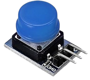
The Blue Button Tact Switch is a momentary push-button switch that is activated when pressed. It is widely used in various electronic devices for user input, allowing users to interact with the device easily. Common applications include remote controls, keyboards, and various consumer electronics. Its compact size and reliable performance make it a popular choice for hobbyists and professionals alike.
Explore Projects Built with Blue Button Tact Switch
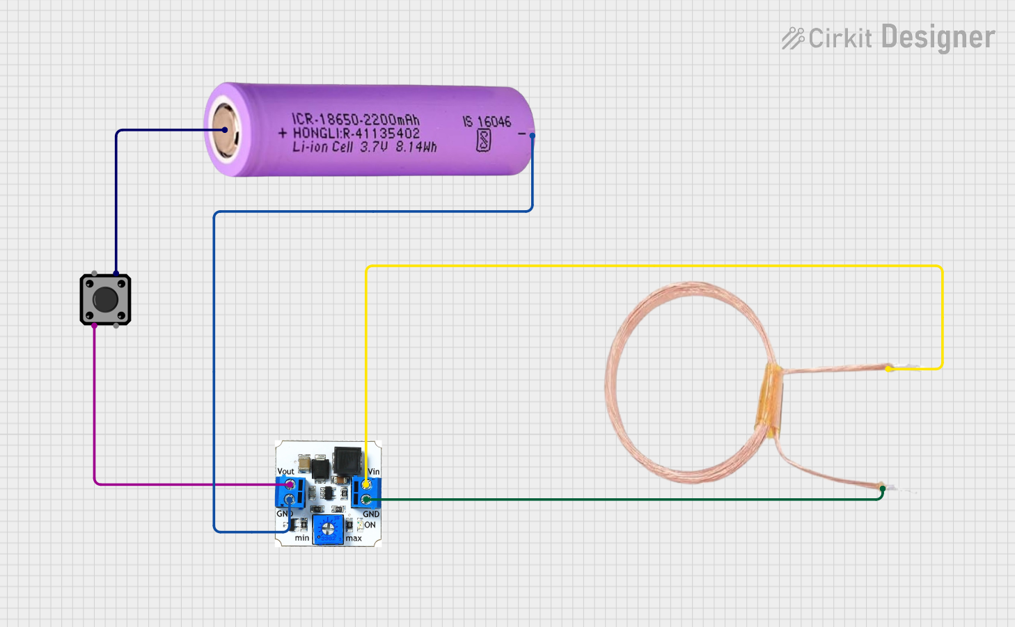
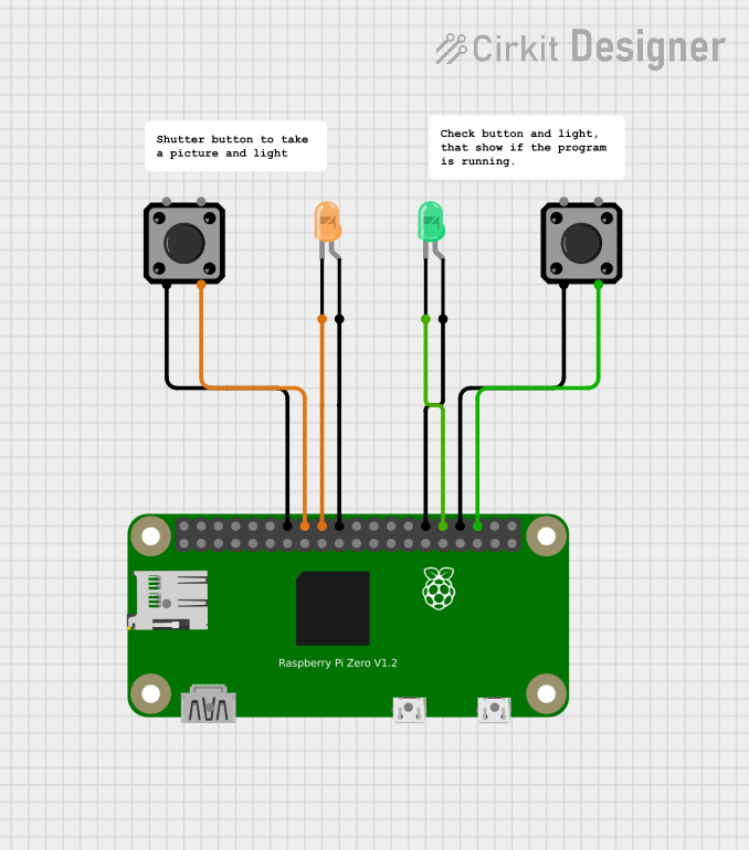


Explore Projects Built with Blue Button Tact Switch
Technical Specifications
Key Technical Details
| Specification | Value |
|---|---|
| Operating Voltage | 12V DC |
| Current Rating | 50mA |
| Power Rating | 0.6W |
| Contact Resistance | < 100 Ohms |
| Actuation Force | 160 - 300g |
| Lifespan | 100,000 cycles |
Pin Configuration
| Pin Number | Pin Name | Description |
|---|---|---|
| 1 | NO | Normally Open - connects when pressed |
| 2 | COM | Common - connects to ground or power |
| 3 | NC | Normally Closed - connects when not pressed (optional) |
Usage Instructions
How to Use the Component in a Circuit
- Wiring: Connect the COM pin to the ground of your circuit. Connect the NO pin to the input pin of your microcontroller (e.g., Arduino). If using the NC pin, connect it to a different circuit path as needed.
- Power Supply: Ensure that the voltage supplied to the switch does not exceed the rated operating voltage (12V DC).
- Debouncing: Implement debouncing in your code to avoid multiple triggers from a single press.
Important Considerations and Best Practices
- Debouncing: Mechanical switches can produce noise when pressed, leading to multiple signals. Use software debouncing techniques in your code.
- Current Limiting: Ensure that the current flowing through the switch does not exceed the rated current (50mA) to prevent damage.
- Mounting: If soldering, ensure that the heat does not exceed the component's tolerance to avoid damage.
Troubleshooting and FAQs
Common Issues Users Might Face
Switch Not Responding:
- Ensure proper connections are made.
- Check for any physical obstructions or damage to the switch.
Multiple Signals on a Single Press:
- This is likely due to switch bounce. Implement debouncing in your code.
Switch Sticking:
- Inspect for debris or damage. Replace the switch if necessary.
Solutions and Tips for Troubleshooting
- Testing the Switch: Use a multimeter to check continuity across the switch pins when pressed.
- Debouncing Code Example: Below is a simple Arduino code snippet to handle debouncing.
const int buttonPin = 2; // Pin connected to the switch
int buttonState;          // Current state of the button
int lastButtonState = LOW; // Previous state of the button
unsigned long lastDebounceTime = 0; // Last time the button state changed
unsigned long debounceDelay = 50; // Debounce time in milliseconds

void setup() {
  pinMode(buttonPin, INPUT);
  Serial.begin(9600);
}

void loop() {
  int reading = digitalRead(buttonPin);

  // Check if the button state has changed
  if (reading != lastButtonState) {
    lastDebounceTime = millis(); // Reset the debounce timer
  }

  // If the button state has been stable for the debounce delay
  if ((millis() - lastDebounceTime) > debounceDelay) {
    // If the button state has changed
    if (reading != buttonState) {
      buttonState = reading; // Update the button state
      // Print the button state to the Serial Monitor
      Serial.println(buttonState == HIGH ? "Button Pressed" : "Button Released");
    }
  }

  lastButtonState = reading; // Save the reading for the next loop
}
This code reads the state of the button and prints whether it is pressed or released, while handling debouncing to ensure accurate readings.
By following this documentation, users can effectively utilize the Blue Button Tact Switch in their electronic projects, ensuring reliable performance and user interaction.