How to Use Adafruit USB Type C Breakout: Examples, Pinouts, and Specs
Introduction
The Adafruit USB Type C Breakout board is a versatile and compact breakout board that simplifies the use of USB Type C connectors in electronic projects. USB Type C connectors are known for their reversibility and high-speed data transfer capabilities. This breakout board is particularly useful for hobbyists, engineers, and designers who want to incorporate USB Type C ports into their projects without the hassle of dealing with a complex connector.
Explore Projects Built with Adafruit USB Type C Breakout


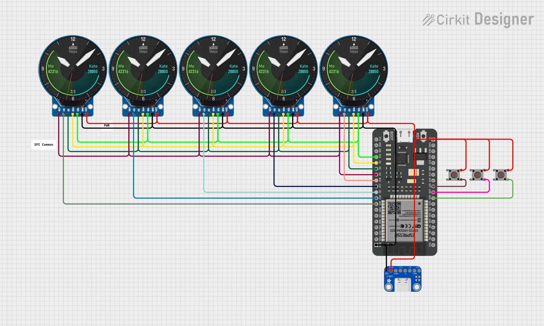
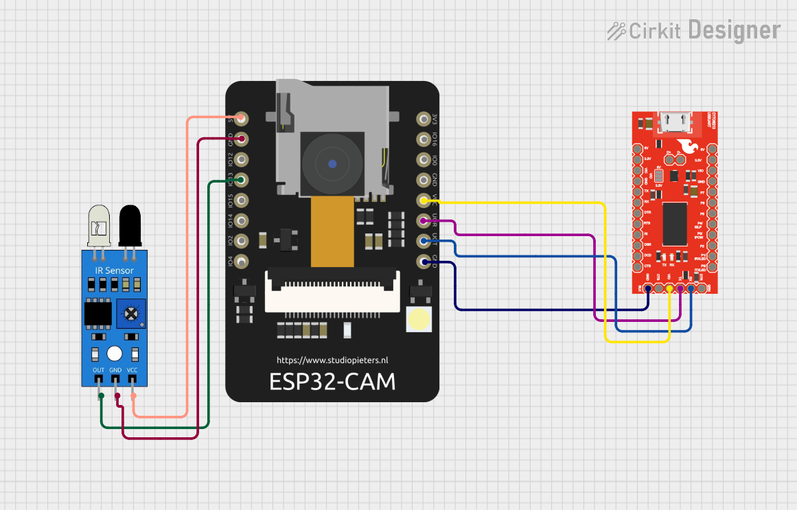
Explore Projects Built with Adafruit USB Type C Breakout
Common Applications and Use Cases
- Power delivery for electronic devices
- Data transfer interfaces for microcontrollers
- USB connectivity for custom-built computers or peripherals
- Prototyping USB Type C enabled devices
- Charging ports for battery-powered projects
Technical Specifications
Key Technical Details
- Voltage Rating: 5V to 20V
- Current Rating: Up to 3A (with proper cable)
- Data Transfer: USB 2.0 speed (up to 480 Mbps)
- Dimensions: 31mm x 10mm x 3mm
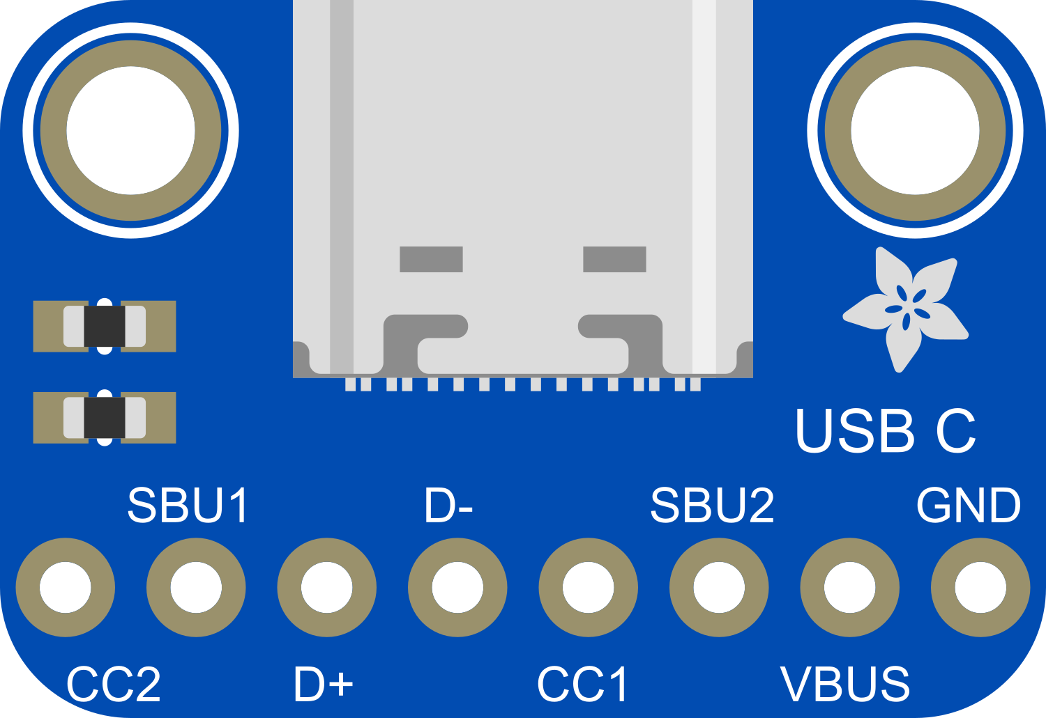
Pin Configuration and Descriptions
| Pin Number | Name | Description |
|---|---|---|
| 1 | VBUS | Power (5V-20V) |
| 2 | D+ | USB Data + |
| 3 | D- | USB Data - |
| 4 | CC1 | Channel Configuration pin 1 |
| 5 | CC2 | Channel Configuration pin 2 |
| 6 | GND | Ground |
Usage Instructions
How to Use the Component in a Circuit
- Power Connections: Connect the VBUS pin to your power source (5V-20V) and the GND pin to the common ground in your circuit.
- Data Connections: Connect the D+ and D- pins to the corresponding data pins on your microcontroller or USB interface chip.
- Channel Configuration: The CC1 and CC2 pins are used to determine cable orientation and set the current mode for power delivery. These pins can be left unconnected for basic applications.
Important Considerations and Best Practices
- Ensure that the power source does not exceed the maximum voltage rating of 20V.
- Use a proper USB Type C cable capable of handling the current if you are using the breakout for power delivery.
- For data transfer applications, ensure that the microcontroller or USB interface chip supports USB 2.0 speeds.
- Always double-check connections before powering up the circuit to prevent damage to the breakout board or other components.
Example Code for Arduino UNO
// This example demonstrates basic USB Type C power delivery using the Adafruit breakout board.
// It does not handle data transfer.

void setup() {
  pinMode(5, OUTPUT); // Assuming VBUS is connected to digital pin 5
  digitalWrite(5, HIGH); // Enable power delivery
}

void loop() {
  // Your code here to interact with other components
}
Troubleshooting and FAQs
Common Issues
- No Power Delivery: Check the cable and ensure it is properly connected and capable of delivering power.
- Data Transfer Not Working: Verify that the D+ and D- connections are correct and that the microcontroller supports USB 2.0.
Solutions and Tips for Troubleshooting
- If the device is not powering on, ensure that the VBUS and GND connections are secure and that the power source is within the specified range.
- For data transfer issues, use a multimeter to check the continuity of the D+ and D- lines.
- If using the breakout for power delivery, ensure that the CC pins are configured correctly for the desired power mode.
FAQs
Q: Can I use this breakout board for USB 3.0 or higher speeds? A: No, this breakout board is designed for USB 2.0 speeds only.
Q: Is it possible to use this board for USB Power Delivery (PD)? A: While the board can handle power delivery up to 3A with the proper cable, it does not include the necessary communication protocol handling for full USB PD compliance.
Q: How do I know if my USB Type C cable is inserted correctly? A: The CC1 and CC2 pins are used to automatically detect the orientation of the cable. You do not need to worry about the cable orientation with this breakout board.
Q: Can I use this breakout board to charge devices? A: Yes, as long as the device's charging requirements do not exceed the breakout board's specifications and you use a suitable USB Type C cable.