Cirkit Designer Logo
Cirkit Designer
Your all-in-one circuit design IDE
Home / 
Component Documentation

How to Use RS485: Examples, Pinouts, and Specs

Image of RS485
Cirkit Designer LogoDesign with RS485 in Cirkit Designer

Introduction

RS485 is a standard for serial communication that enables reliable, long-distance data transmission. It supports multiple devices on a single bus, making it ideal for multi-point communication. RS485 is widely used in industrial applications due to its robustness, noise immunity, and ability to operate over extended distances. It is commonly employed in systems such as building automation, industrial control systems, and data acquisition networks.

Explore Projects Built with RS485

Use Cirkit Designer to design, explore, and prototype these projects online. Some projects support real-time simulation. Click "Open Project" to start designing instantly!
STM32 and Arduino UNO Based Dual RS485 Communication Interface
Image of STM to Arduino RS485: A project utilizing RS485 in a practical application
This circuit consists of two microcontrollers, an STM32F103C8T6 and an Arduino UNO, each interfaced with separate RS485 transceiver modules for serial communication. The STM32F103C8T6 controls the RE (Receiver Enable) and DE (Driver Enable) pins of one RS485 module to manage its operation, and communicates via the A9 and A10 pins for DI (Data Input) and RO (Receiver Output), respectively. The Arduino UNO is similarly connected to another RS485 module, with digital pins D2 and D3 interfacing with DI and RO, and D8 controlling both RE and DE. The RS485 modules are connected to each other through their A and B differential communication lines, enabling serial data exchange between the two microcontrollers over a robust and long-distance capable RS485 network.
Cirkit Designer LogoOpen Project in Cirkit Designer
Arduino UNO and Relay-Controlled RS485 Communication System
Image of Diagrama: A project utilizing RS485 in a practical application
This circuit features an Arduino UNO microcontroller interfaced with a 4-channel relay module and a UART TTL to RS485 converter. The Arduino controls the relays via digital pins and communicates with the RS485 converter for serial communication, enabling control of external devices and communication over long distances.
Cirkit Designer LogoOpen Project in Cirkit Designer
RS485-Enabled NPK Soil Sensor Interface
Image of NPK: A project utilizing RS485 in a practical application
This circuit connects an NPK Soil Sensor to an RS485 transceiver module. The sensor's VCC and GND pins are connected to the corresponding VCC and GND pins on the RS485 module to provide power. The sensor's analog output (A) and digital output (B) are interfaced with the RS485 module's DI (Data Input) and DE (Driver Enable) pins, respectively, allowing the sensor's signals to be transmitted over an RS485 communication bus.
Cirkit Designer LogoOpen Project in Cirkit Designer
ESP32C3-Based Soil Monitoring System with RS485 Communication
Image of 3-slave-soil: A project utilizing RS485 in a practical application
This circuit features an ESP32C3 Supermini microcontroller interfaced with an RS485 transceiver module, allowing for serial communication over long distances. A toggle switch and a pushbutton are connected to the ESP32C3 for user input, with a pull-up resistor on the toggle switch. Additionally, the circuit includes an NPK Soil Sensor connected to the RS485 module for measuring soil nutrient levels, with power supplied to the sensor and RS485 module from the ESP32C3.
Cirkit Designer LogoOpen Project in Cirkit Designer

Explore Projects Built with RS485

Use Cirkit Designer to design, explore, and prototype these projects online. Some projects support real-time simulation. Click "Open Project" to start designing instantly!
Image of STM to Arduino RS485: A project utilizing RS485 in a practical application
STM32 and Arduino UNO Based Dual RS485 Communication Interface
This circuit consists of two microcontrollers, an STM32F103C8T6 and an Arduino UNO, each interfaced with separate RS485 transceiver modules for serial communication. The STM32F103C8T6 controls the RE (Receiver Enable) and DE (Driver Enable) pins of one RS485 module to manage its operation, and communicates via the A9 and A10 pins for DI (Data Input) and RO (Receiver Output), respectively. The Arduino UNO is similarly connected to another RS485 module, with digital pins D2 and D3 interfacing with DI and RO, and D8 controlling both RE and DE. The RS485 modules are connected to each other through their A and B differential communication lines, enabling serial data exchange between the two microcontrollers over a robust and long-distance capable RS485 network.
Cirkit Designer LogoOpen Project in Cirkit Designer
Image of Diagrama: A project utilizing RS485 in a practical application
Arduino UNO and Relay-Controlled RS485 Communication System
This circuit features an Arduino UNO microcontroller interfaced with a 4-channel relay module and a UART TTL to RS485 converter. The Arduino controls the relays via digital pins and communicates with the RS485 converter for serial communication, enabling control of external devices and communication over long distances.
Cirkit Designer LogoOpen Project in Cirkit Designer
Image of NPK: A project utilizing RS485 in a practical application
RS485-Enabled NPK Soil Sensor Interface
This circuit connects an NPK Soil Sensor to an RS485 transceiver module. The sensor's VCC and GND pins are connected to the corresponding VCC and GND pins on the RS485 module to provide power. The sensor's analog output (A) and digital output (B) are interfaced with the RS485 module's DI (Data Input) and DE (Driver Enable) pins, respectively, allowing the sensor's signals to be transmitted over an RS485 communication bus.
Cirkit Designer LogoOpen Project in Cirkit Designer
Image of 3-slave-soil: A project utilizing RS485 in a practical application
ESP32C3-Based Soil Monitoring System with RS485 Communication
This circuit features an ESP32C3 Supermini microcontroller interfaced with an RS485 transceiver module, allowing for serial communication over long distances. A toggle switch and a pushbutton are connected to the ESP32C3 for user input, with a pull-up resistor on the toggle switch. Additionally, the circuit includes an NPK Soil Sensor connected to the RS485 module for measuring soil nutrient levels, with power supplied to the sensor and RS485 module from the ESP32C3.
Cirkit Designer LogoOpen Project in Cirkit Designer

Technical Specifications

  • Communication Standard: RS485 (TIA/EIA-485)
  • Maximum Data Rate: Up to 10 Mbps (short distances)
  • Maximum Cable Length: Up to 1200 meters (at lower data rates, typically 100 kbps)
  • Number of Devices: Supports up to 32 drivers and 32 receivers on a single bus
  • Voltage Levels: Differential signaling with typical voltage levels of ±1.5V to ±5V
  • Termination: Requires termination resistors at both ends of the bus to prevent signal reflections
  • Connector Type: Typically uses screw terminals or DB9 connectors

Pin Configuration and Descriptions

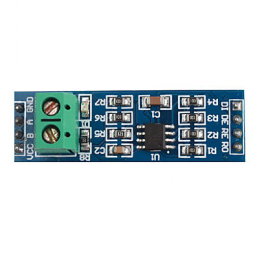
The RS485 transceiver typically has the following pin configuration:

Pin Name Description
A (D+) Non-inverting differential signal line (positive data line)
B (D-) Inverting differential signal line (negative data line)
GND Ground reference for the communication bus
VCC Power supply for the transceiver (commonly 3.3V or 5V)
DE Driver Enable: Activates the driver for transmitting data
RE Receiver Enable: Activates the receiver for receiving data
DI Data Input: Input data to be transmitted (connected to the microcontroller)
RO Receiver Output: Output data received from the bus (connected to the microcontroller)

Usage Instructions

How to Use RS485 in a Circuit

  1. Connect the RS485 Transceiver:

    • Connect the A (D+) and B (D-) pins to the RS485 bus.
    • Attach termination resistors (typically 120 ohms) at both ends of the bus to reduce signal reflections.
    • Connect the GND pin to the ground of the system.
    • Provide power to the VCC pin (3.3V or 5V, depending on the transceiver).
  2. Enable Communication:

    • Use the DE (Driver Enable) pin to control when the transceiver sends data. Set DE high to enable transmission.
    • Use the RE (Receiver Enable) pin to control when the transceiver receives data. Set RE low to enable reception.
  3. Connect to a Microcontroller:

    • Connect the DI pin to the microcontroller's TX (transmit) pin.
    • Connect the RO pin to the microcontroller's RX (receive) pin.
  4. Write Code for Communication:

    • Use a UART (Universal Asynchronous Receiver-Transmitter) interface on the microcontroller to send and receive data over RS485.

Example Code for Arduino UNO

Below is an example of how to use RS485 with an Arduino UNO:

#include <SoftwareSerial.h>

// Define RS485 pins
#define DE_PIN 2  // Driver Enable pin
#define RE_PIN 3  // Receiver Enable pin
#define TX_PIN 4  // TX pin for RS485
#define RX_PIN 5  // RX pin for RS485

// Create a SoftwareSerial object for RS485 communication
SoftwareSerial RS485Serial(RX_PIN, TX_PIN);

void setup() {
  // Initialize serial communication
  Serial.begin(9600);          // For debugging via Serial Monitor
  RS485Serial.begin(9600);     // RS485 communication baud rate

  // Set DE and RE pins as outputs
  pinMode(DE_PIN, OUTPUT);
  pinMode(RE_PIN, OUTPUT);

  // Set RS485 to receive mode initially
  digitalWrite(DE_PIN, LOW);   // Disable driver
  digitalWrite(RE_PIN, LOW);   // Enable receiver
}

void loop() {
  // Example: Send data over RS485
  digitalWrite(DE_PIN, HIGH);  // Enable driver
  digitalWrite(RE_PIN, HIGH);  // Disable receiver
  RS485Serial.println("Hello, RS485!");  // Send data
  delay(100);                  // Short delay to ensure data is sent
  digitalWrite(DE_PIN, LOW);   // Disable driver
  digitalWrite(RE_PIN, LOW);   // Enable receiver

  // Example: Receive data over RS485
  if (RS485Serial.available()) {
    String receivedData = RS485Serial.readString();
    Serial.println("Received: " + receivedData);  // Print received data
  }

  delay(1000);  // Wait before next iteration
}

Important Considerations

  • Termination Resistors: Always use termination resistors at both ends of the RS485 bus to prevent signal reflections and ensure reliable communication.
  • Biasing Resistors: Use pull-up and pull-down resistors on the A and B lines to maintain a known idle state when no devices are transmitting.
  • Grounding: Ensure all devices on the RS485 bus share a common ground to avoid communication errors.
  • Bus Length and Data Rate: The maximum cable length decreases as the data rate increases. Choose appropriate settings based on your application.

Troubleshooting and FAQs

Common Issues and Solutions

  1. No Communication Between Devices:

    • Verify the wiring of the A (D+) and B (D-) lines. Ensure they are not swapped.
    • Check that the DE and RE pins are correctly controlled for transmission and reception.
  2. Data Corruption or Noise:

    • Ensure termination resistors are installed at both ends of the RS485 bus.
    • Use shielded twisted-pair cables to reduce electromagnetic interference (EMI).
  3. Devices Not Responding:

    • Confirm that all devices share a common ground.
    • Check the power supply voltage and ensure it matches the transceiver's requirements.
  4. Communication Fails Over Long Distances:

    • Reduce the data rate to improve signal integrity over long distances.
    • Use repeaters if the cable length exceeds 1200 meters.

FAQs

  • Q: Can RS485 support full-duplex communication?
    A: RS485 is inherently half-duplex, but full-duplex communication can be achieved by using two separate RS485 transceivers.

  • Q: How many devices can I connect to an RS485 bus?
    A: RS485 supports up to 32 drivers and 32 receivers. However, modern transceivers may allow more devices.

  • Q: Do I need special software to use RS485?
    A: No, RS485 uses standard UART communication, which is supported by most microcontrollers.

  • Q: Can I use RS485 for wireless communication?
    A: RS485 is a wired communication standard. For wireless communication, consider using protocols like Zigbee or LoRa.