Cirkit Designer Logo
Cirkit Designer
Your all-in-one circuit design IDE
Home / 
Component Documentation

How to Use ldr 2: Examples, Pinouts, and Specs

Image of ldr 2
Cirkit Designer LogoDesign with ldr 2 in Cirkit Designer

Introduction

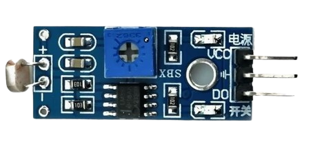
A Light Dependent Resistor (LDR), also known as a photoresistor, is a passive electronic component whose resistance decreases as the intensity of incident light increases. This property makes it an ideal choice for light-sensing applications. The LDR 2 is a standard light-dependent resistor with moderate sensitivity and is widely used in circuits requiring light detection or automatic light control.

Explore Projects Built with ldr 2

Use Cirkit Designer to design, explore, and prototype these projects online. Some projects support real-time simulation. Click "Open Project" to start designing instantly!
LDR-Controlled LED Lighting System
Image of automatic street light: A project utilizing ldr 2 in a practical application
This circuit appears to be a simple light-detection system that uses an LDR (Light Dependent Resistor) to control the state of multiple green LEDs. The LDR's analog output (AO) is not connected, suggesting that the circuit uses the digital output (DO) to directly drive one LED, while the other LEDs are wired in parallel to the LDR's power supply (Vcc). The Pd (presumably a power distribution component) provides the necessary voltage levels to the LDR and LEDs.
Cirkit Designer LogoOpen Project in Cirkit Designer
Arduino UNO Light Sensor with LED Indicator
Image of lesson9: A project utilizing ldr 2 in a practical application
This circuit uses an Arduino UNO to read data from a Light Dependent Resistor (LDR) module and control a red LED. The LDR is powered by the Arduino and its analog output is connected to the Arduino's A2 pin, while the LED is connected to digital pin D3 through a 200-ohm resistor.
Cirkit Designer LogoOpen Project in Cirkit Designer
Arduino UNO Based LDR-Controlled LED Indicator
Image of switch: A project utilizing ldr 2 in a practical application
This circuit features an Arduino UNO connected to an LDR (Light Dependent Resistor) module and an LED with a series resistor. The LDR module is powered by the Arduino's 5V output and its digital output (DO) is connected to the Arduino's analog input A0, potentially for light level sensing. The LED is connected to digital pin D13 through a 220 Ohm resistor, which could be used to indicate the status or the result of the LDR's light sensing.
Cirkit Designer LogoOpen Project in Cirkit Designer
Arduino 101 Light-Activated LED with LDR Sensor
Image of automatic street light LK: A project utilizing ldr 2 in a practical application
This circuit uses an Arduino 101 to control an LED based on the input from a Light Dependent Resistor (LDR) module. When the LDR detects low light levels, the Arduino turns on the LED by setting the output pin high.
Cirkit Designer LogoOpen Project in Cirkit Designer

Explore Projects Built with ldr 2

Use Cirkit Designer to design, explore, and prototype these projects online. Some projects support real-time simulation. Click "Open Project" to start designing instantly!
Image of automatic street light: A project utilizing ldr 2 in a practical application
LDR-Controlled LED Lighting System
This circuit appears to be a simple light-detection system that uses an LDR (Light Dependent Resistor) to control the state of multiple green LEDs. The LDR's analog output (AO) is not connected, suggesting that the circuit uses the digital output (DO) to directly drive one LED, while the other LEDs are wired in parallel to the LDR's power supply (Vcc). The Pd (presumably a power distribution component) provides the necessary voltage levels to the LDR and LEDs.
Cirkit Designer LogoOpen Project in Cirkit Designer
Image of lesson9: A project utilizing ldr 2 in a practical application
Arduino UNO Light Sensor with LED Indicator
This circuit uses an Arduino UNO to read data from a Light Dependent Resistor (LDR) module and control a red LED. The LDR is powered by the Arduino and its analog output is connected to the Arduino's A2 pin, while the LED is connected to digital pin D3 through a 200-ohm resistor.
Cirkit Designer LogoOpen Project in Cirkit Designer
Image of switch: A project utilizing ldr 2 in a practical application
Arduino UNO Based LDR-Controlled LED Indicator
This circuit features an Arduino UNO connected to an LDR (Light Dependent Resistor) module and an LED with a series resistor. The LDR module is powered by the Arduino's 5V output and its digital output (DO) is connected to the Arduino's analog input A0, potentially for light level sensing. The LED is connected to digital pin D13 through a 220 Ohm resistor, which could be used to indicate the status or the result of the LDR's light sensing.
Cirkit Designer LogoOpen Project in Cirkit Designer
Image of automatic street light LK: A project utilizing ldr 2 in a practical application
Arduino 101 Light-Activated LED with LDR Sensor
This circuit uses an Arduino 101 to control an LED based on the input from a Light Dependent Resistor (LDR) module. When the LDR detects low light levels, the Arduino turns on the LED by setting the output pin high.
Cirkit Designer LogoOpen Project in Cirkit Designer

Common Applications and Use Cases

  • Automatic street lighting systems
  • Light intensity measurement devices
  • Alarm systems triggered by light changes
  • Solar tracking systems
  • Brightness control in displays

Technical Specifications

Below are the key technical details of the LDR 2:

Parameter Value
Resistance (Dark) 1 MΩ (typical)
Resistance (Bright) 1 kΩ to 10 kΩ (typical)
Maximum Voltage 150 V
Power Dissipation 100 mW
Response Time (Rise) 20 ms
Response Time (Fall) 30 ms
Operating Temperature -30°C to +70°C
Material Cadmium Sulfide (CdS)

Pin Configuration and Descriptions

The LDR 2 is a two-terminal device. The pins are not polarized, meaning it can be connected in either direction in a circuit.

Pin Description
Pin 1 One terminal of the resistor
Pin 2 The other terminal of the resistor

Usage Instructions

How to Use the LDR 2 in a Circuit

  1. Basic Circuit Connection:

    • Connect one terminal of the LDR to a voltage source (e.g., 5V).
    • Connect the other terminal to a pull-down resistor (e.g., 10 kΩ) and then to ground.
    • The junction between the LDR and the pull-down resistor serves as the output voltage point, which varies with light intensity.
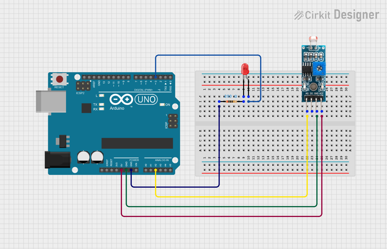
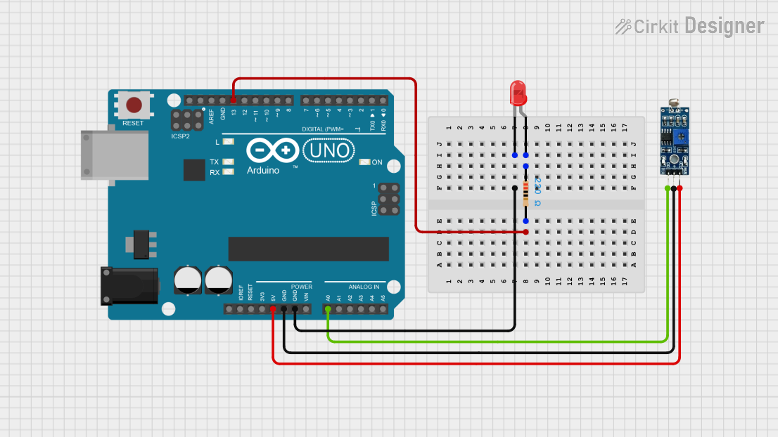
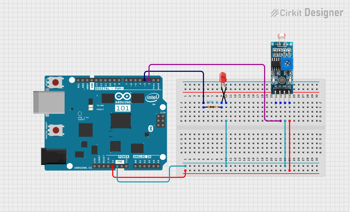
  2. Interfacing with an Arduino UNO:

    • Connect the LDR and a pull-down resistor as described above.
    • Connect the output voltage point to an analog input pin (e.g., A0) on the Arduino UNO.
    • Use the following code to read and display the light intensity:
// Arduino code to read LDR values and display them on the Serial Monitor

const int ldrPin = A0; // Define the analog pin connected to the LDR

void setup() {
  Serial.begin(9600); // Initialize serial communication at 9600 baud
}

void loop() {
  int ldrValue = analogRead(ldrPin); // Read the analog value from the LDR
  Serial.print("LDR Value: ");       // Print a label for the value
  Serial.println(ldrValue);          // Print the LDR value
  delay(500);                        // Wait for 500 ms before the next reading
}

Important Considerations and Best Practices

  • Avoid Overvoltage: Ensure the voltage across the LDR does not exceed its maximum rating of 150 V.
  • Use a Suitable Pull-Down Resistor: The value of the pull-down resistor should be chosen based on the expected light conditions. A 10 kΩ resistor is a good starting point for most applications.
  • Protect from Extreme Conditions: Avoid exposing the LDR to temperatures beyond its operating range (-30°C to +70°C) or to excessive humidity, as this may degrade its performance.
  • Response Time: Note that the LDR has a slower response time compared to photodiodes or phototransistors, making it less suitable for high-speed light detection.

Troubleshooting and FAQs

Common Issues and Solutions

  1. No Change in Output Voltage:

    • Cause: The LDR may not be exposed to sufficient light variation.
    • Solution: Test the circuit in varying light conditions or use a flashlight to simulate changes in light intensity.
  2. Output Voltage is Always High or Low:

    • Cause: Incorrect pull-down resistor value or a faulty LDR.
    • Solution: Verify the pull-down resistor value and replace the LDR if necessary.
  3. Inconsistent Readings:

    • Cause: Electrical noise or loose connections.
    • Solution: Use shorter wires, ensure secure connections, and consider adding a capacitor across the LDR terminals to filter noise.

FAQs

Q1: Can the LDR 2 detect infrared light?
A1: The LDR 2 is primarily sensitive to visible light. It has limited sensitivity to infrared light and is not ideal for IR-specific applications.

Q2: How do I choose the pull-down resistor value?
A2: The pull-down resistor value depends on the expected light intensity range. For general use, a 10 kΩ resistor works well. For low-light conditions, a higher resistance (e.g., 100 kΩ) may be more suitable.

Q3: Can I use the LDR 2 in outdoor applications?
A3: Yes, but ensure the LDR is protected from moisture and extreme temperatures. Use a weatherproof enclosure if necessary.

Q4: What is the lifespan of the LDR 2?
A4: The LDR 2 has a long lifespan if operated within its specified limits. However, prolonged exposure to high temperatures or humidity can reduce its performance over time.