
How to Use SIM7600E Module: Examples, Pinouts, and Specs
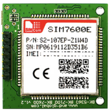
 Design with SIM7600E Module in Cirkit Designer
Introduction
The SIM7600E is a 4G LTE module designed to provide high-speed mobile data connectivity for IoT (Internet of Things) applications. It supports multiple communication protocols, including LTE, GSM, GPRS, and EDGE, making it a versatile choice for projects requiring reliable wireless communication. Additionally, the module features GPS functionality, enabling location-based services.
Explore Projects Built with SIM7600E Module
 Open Project in Cirkit Designer
 Open Project in Cirkit Designer
 Open Project in Cirkit Designer
 Open Project in Cirkit Designer
Explore Projects Built with SIM7600E Module
Open Project in Cirkit DesignerOpen Project in Cirkit DesignerOpen Project in Cirkit DesignerOpen Project in Cirkit DesignerCommon Applications and Use Cases
- IoT devices requiring cellular connectivity
- GPS tracking and navigation systems
- Remote monitoring and control systems
- Smart home and industrial automation
- Vehicle telematics and fleet management
- Mobile payment terminals
Technical Specifications
Key Technical Details
| Parameter | Specification |
|---|---|
| Cellular Network Support | LTE, GSM, GPRS, EDGE |
| LTE Bands | B1/B3/B5/B7/B8/B20/B28 |
| Data Rates (LTE) | Uplink: 50 Mbps, Downlink: 150 Mbps |
| GPS Support | Yes (GNSS: GPS, GLONASS, BeiDou) |
| Operating Voltage | 3.4V to 4.2V |
| Power Consumption | Idle: ~20mA, Active: ~500mA |
| Operating Temperature | -40°C to +85°C |
| Communication Interfaces | UART, USB, I2C, GPIO, ADC |
| Dimensions | 30mm x 30mm x 2.9mm |
Pin Configuration and Descriptions
| Pin Number | Pin Name | Description |
|---|---|---|
| 1 | VCC | Power supply input (3.4V to 4.2V) |
| 2 | GND | Ground |
| 3 | TXD | UART Transmit Data |
| 4 | RXD | UART Receive Data |
| 5 | USB_D+ | USB Data Positive |
| 6 | USB_D- | USB Data Negative |
| 7 | NET_STATUS | Network status indicator |
| 8 | PWRKEY | Power on/off control pin |
| 9 | GNSS_TXD | GNSS UART Transmit Data |
| 10 | GNSS_RXD | GNSS UART Receive Data |
| 11 | ADC_IN | Analog-to-Digital Converter input |
| 12 | GPIO1 | General-purpose input/output |
Usage Instructions
How to Use the SIM7600E Module in a Circuit
- Power Supply: Connect the VCC pin to a stable 3.7V power source and GND to ground. Ensure the power supply can handle peak currents of up to 2A.
- UART Communication: Connect the TXD and RXD pins to the corresponding UART pins of your microcontroller (e.g., Arduino UNO). Use a logic level converter if your microcontroller operates at 5V logic.
- Power On: Pull the PWRKEY pin low for at least 1 second to turn on the module.
- Antenna Connection: Attach a compatible LTE antenna to the module's antenna connector for optimal signal reception.
- GPS Functionality: If GPS is required, connect the GNSS_TXD and GNSS_RXD pins to your microcontroller's UART interface and attach a GPS antenna.
- USB Interface: For direct communication with a PC, connect the USB_D+ and USB_D- pins to a USB port using a USB cable.
Important Considerations and Best Practices
- Use decoupling capacitors near the VCC pin to stabilize the power supply.
- Ensure proper grounding to minimize noise and interference.
- Place the antennas away from high-frequency components to avoid signal degradation.
- Use appropriate baud rates (e.g., 115200 bps) for UART communication.
- Follow the manufacturer's guidelines for firmware updates and AT command usage.
Example Code for Arduino UNO
Below is an example of how to send an SMS using the SIM7600E module with an Arduino UNO:
#include <SoftwareSerial.h>

// Define RX and TX pins for SoftwareSerial
SoftwareSerial sim7600(10, 11); // RX = pin 10, TX = pin 11

void setup() {
  // Initialize serial communication
  Serial.begin(9600); // For debugging
  sim7600.begin(115200); // SIM7600E baud rate

  // Power on the SIM7600E module
  pinMode(9, OUTPUT); // PWRKEY pin connected to Arduino pin 9
  digitalWrite(9, LOW);
  delay(1000); // Hold PWRKEY low for 1 second
  digitalWrite(9, HIGH);

  // Wait for the module to initialize
  delay(5000);

  // Send AT commands to configure the module
  sendCommand("AT");
  sendCommand("AT+CMGF=1"); // Set SMS mode to text
  sendCommand("AT+CMGS=\"+1234567890\""); // Replace with recipient's phone number
  sim7600.print("Hello, this is a test SMS from SIM7600E!"); // SMS content
  sim7600.write(26); // Send Ctrl+Z to send the SMS
}

void loop() {
  // Check for responses from the module
  if (sim7600.available()) {
    Serial.write(sim7600.read());
  }
}

// Function to send AT commands
void sendCommand(String command) {
  sim7600.println(command);
  delay(1000); // Wait for the module to process the command
}
Troubleshooting and FAQs
Common Issues and Solutions
Module Not Powering On:
- Ensure the PWRKEY pin is pulled low for at least 1 second during startup.
- Verify the power supply voltage is within the 3.4V to 4.2V range and can handle peak currents.
No Network Connection:
- Check the antenna connection and ensure it is securely attached.
- Verify that the SIM card is properly inserted and activated.
- Use the
AT+CSQcommand to check signal strength (higher values indicate better signal).
GPS Not Working:
- Ensure the GPS antenna is connected and placed in an open area with a clear view of the sky.
- Use the
AT+CGNSPWR=1command to enable GPS functionality.
No Response to AT Commands:
- Confirm the UART connections (TXD, RXD) are correct.
- Check the baud rate settings on both the module and the microcontroller.
FAQs
Q: Can the SIM7600E module work with 5V logic?
A: No, the module operates at 3.3V logic. Use a level shifter if your microcontroller uses 5V logic.Q: What is the maximum data rate supported by the module?
A: The SIM7600E supports up to 150 Mbps downlink and 50 Mbps uplink on LTE networks.Q: How can I update the firmware?
A: Firmware updates can be performed via the USB interface using the manufacturer's tools and instructions.Q: Does the module support voice calls?
A: Yes, the SIM7600E supports voice calls in addition to SMS and data communication.