
How to Use TP5100 (LED PINS): Examples, Pinouts, and Specs
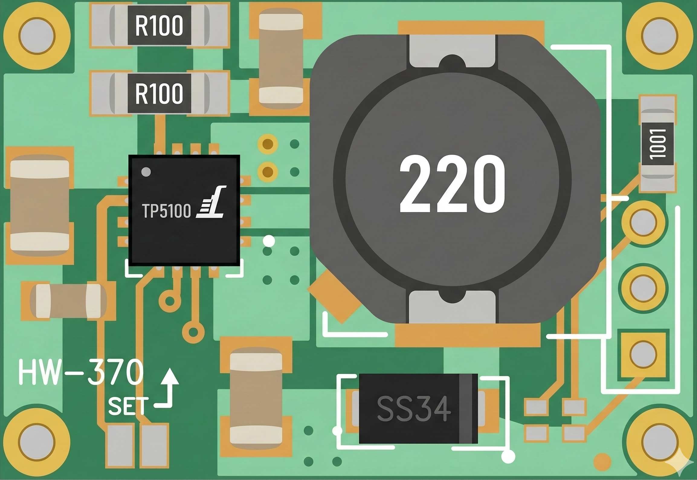
 Design with TP5100 (LED PINS) in Cirkit Designer
Introduction
The TP5100 is a linear voltage regulator specifically designed for LED applications. It provides a stable and efficient output voltage to drive LED circuits, ensuring consistent brightness and performance. With its integrated current regulation and multiple LED pin connections, the TP5100 is ideal for powering LED arrays in various lighting and display applications.
Explore Projects Built with TP5100 (LED PINS)
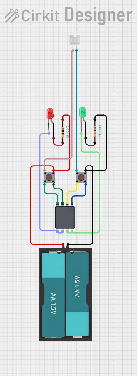 Open Project in Cirkit Designer
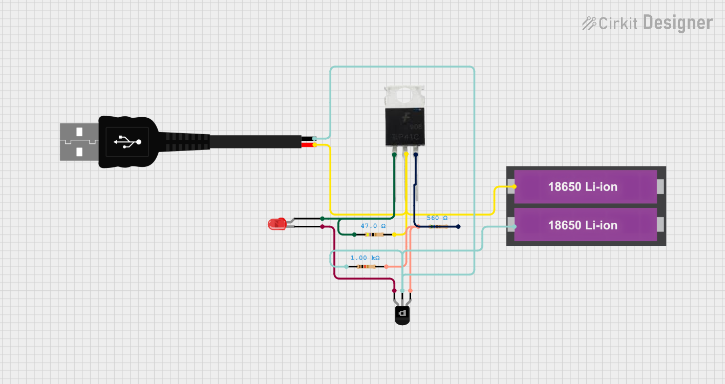 Open Project in Cirkit Designer
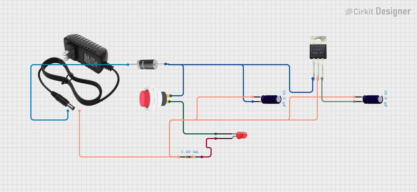 Open Project in Cirkit Designer
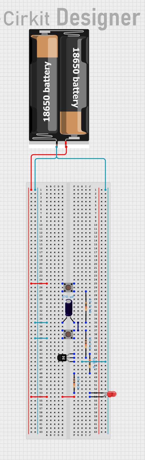 Open Project in Cirkit Designer
Explore Projects Built with TP5100 (LED PINS)
Open Project in Cirkit DesignerOpen Project in Cirkit DesignerOpen Project in Cirkit DesignerOpen Project in Cirkit DesignerCommon Applications
- LED lighting systems
- LED backlighting for displays
- Automotive LED applications
- Decorative and architectural lighting
- Battery-powered LED devices
Technical Specifications
The TP5100 is designed to deliver reliable performance in LED circuits. Below are its key technical specifications:
| Parameter | Value |
|---|---|
| Input Voltage Range | 4.5V to 18V |
| Output Voltage | 3.3V or 5V (adjustable) |
| Maximum Output Current | 2A |
| Efficiency | Up to 90% |
| Operating Temperature | -40°C to +85°C |
| LED Pin Current Regulation | 10mA to 1A (adjustable) |
Pin Configuration and Descriptions
The TP5100 features multiple pins for connecting LEDs and other components. Below is the pinout description:
| Pin Number | Pin Name | Description |
|---|---|---|
| 1 | VIN | Input voltage pin. Connect to the power supply (4.5V to 18V). |
| 2 | GND | Ground pin. Connect to the circuit ground. |
| 3 | VOUT | Regulated output voltage pin. Connect to the LED circuit. |
| 4 | LED+ | Positive terminal for LED connection. |
| 5 | LED- | Negative terminal for LED connection. |
| 6 | ADJ | Adjustment pin for setting the output voltage or current. |
| 7 | EN | Enable pin. Used to turn the regulator on or off. |
| 8 | NC | No connection. Leave this pin unconnected. |
Usage Instructions
How to Use the TP5100 in a Circuit
- Power Supply Connection: Connect the VIN pin to a DC power source within the range of 4.5V to 18V. Ensure the power supply can provide sufficient current for the LEDs.
- Ground Connection: Connect the GND pin to the circuit ground.
- LED Connection:
- Connect the positive terminal of the LED array to the LED+ pin.
- Connect the negative terminal of the LED array to the LED- pin.
- Output Voltage Adjustment: Use the ADJ pin to set the desired output voltage or current. This can be done by connecting a resistor or potentiometer to the ADJ pin as specified in the datasheet.
- Enable Pin: If you want to control the regulator's operation, connect the EN pin to a microcontroller or switch. Pulling the EN pin high enables the regulator, while pulling it low disables it.
Important Considerations
- Heat Dissipation: The TP5100 may generate heat during operation, especially at higher currents. Use a heatsink or ensure proper ventilation to prevent overheating.
- Current Limiting: Ensure the current through the LED pins does not exceed the maximum rating of 1A to avoid damage.
- Capacitor Selection: Place appropriate input and output capacitors close to the VIN and VOUT pins to ensure stable operation.
- Reverse Polarity Protection: Add a diode at the input to protect the TP5100 from reverse polarity connections.
Example: Using TP5100 with Arduino UNO
The TP5100 can be controlled using an Arduino UNO to enable or disable the LED circuit. Below is an example code snippet:
// Example code to control the TP5100 Enable pin using Arduino UNO

const int enablePin = 7; // Connect the EN pin of TP5100 to Arduino pin 7

void setup() {
  pinMode(enablePin, OUTPUT); // Set the enable pin as an output
  digitalWrite(enablePin, LOW); // Start with the TP5100 disabled
}

void loop() {
  // Turn on the TP5100 to power the LEDs
  digitalWrite(enablePin, HIGH);
  delay(5000); // Keep LEDs on for 5 seconds

  // Turn off the TP5100 to disable the LEDs
  digitalWrite(enablePin, LOW);
  delay(5000); // Keep LEDs off for 5 seconds
}
Troubleshooting and FAQs
Common Issues and Solutions
LEDs Not Lighting Up
- Cause: Incorrect wiring or insufficient input voltage.
- Solution: Double-check the connections to the LED+ and LED- pins. Ensure the input voltage is within the specified range.
Overheating
- Cause: Excessive current draw or inadequate heat dissipation.
- Solution: Reduce the current through the LEDs or add a heatsink to the TP5100.
Flickering LEDs
- Cause: Insufficient input or output capacitance.
- Solution: Add or replace capacitors at the VIN and VOUT pins with appropriate values.
No Output Voltage
- Cause: EN pin not properly configured.
- Solution: Ensure the EN pin is pulled high to enable the regulator.
FAQs
Q1: Can the TP5100 drive multiple LEDs in series?
A1: Yes, the TP5100 can drive multiple LEDs in series, provided the total forward voltage of the LEDs does not exceed the output voltage.
Q2: How do I adjust the output current for my LEDs?
A2: Use a resistor or potentiometer connected to the ADJ pin to set the desired current. Refer to the datasheet for the resistor value calculations.
Q3: Is the TP5100 suitable for battery-powered applications?
A3: Yes, the TP5100 is efficient and can be used in battery-powered LED circuits. Ensure the input voltage is within the specified range.
Q4: Can I use the TP5100 without connecting the EN pin?
A4: Yes, the TP5100 will operate by default if the EN pin is left floating or pulled high. However, connecting the EN pin to a microcontroller allows for better control.