How to Use 10 Segment LED RED|: Examples, Pinouts, and Specs
Introduction
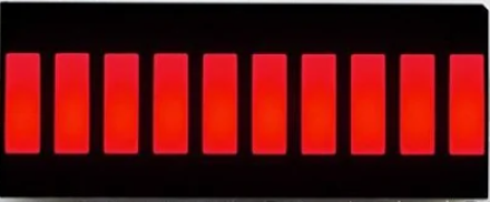
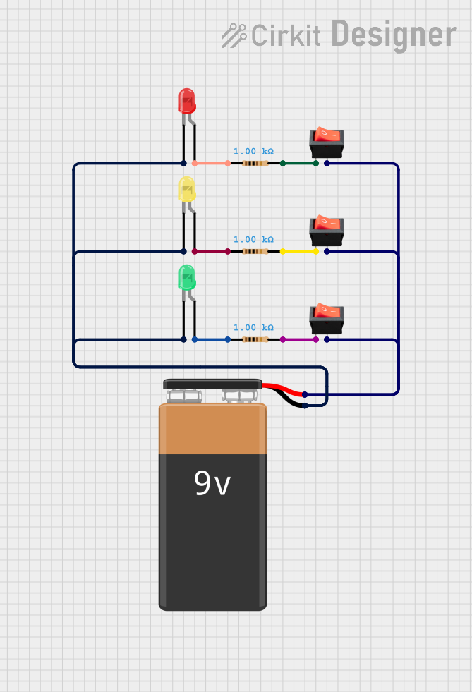
The Kingbright DC10YWA is a 10-segment LED display designed for visual indication and numerical representation. Each segment is a red light-emitting diode (LED) that can be individually controlled to display a variety of patterns, levels, or numerical values. This component is widely used in applications such as audio level meters, battery level indicators, and other digital displays requiring a clear and compact visual output.
Explore Projects Built with 10 Segment LED RED|
Explore Projects Built with 10 Segment LED RED|
Common Applications
- Audio level indicators (VU meters)
- Battery charge level displays
- Signal strength meters
- Industrial control panels
- DIY electronics projects
Technical Specifications
The following table outlines the key technical details of the Kingbright DC10YWA 10-segment LED display:
| Parameter | Value |
|---|---|
| Manufacturer | Kingbright |
| Part Number | DC10YWA |
| LED Color | Red |
| Number of Segments | 10 |
| Forward Voltage (per LED) | 2.0V (typical), 2.5V (max) |
| Forward Current (per LED) | 20mA (typical), 25mA (max) |
| Peak Wavelength | 630nm |
| Luminous Intensity | 2.0mcd (typical) |
| Operating Temperature | -40°C to +85°C |
| Dimensions | 25.4mm x 10mm x 7mm |
| Display Type | Bar Graph |
Pin Configuration and Descriptions
The DC10YWA has 20 pins, with each segment connected to a cathode or anode pin. The display is available in a common cathode configuration. Below is the pinout for the component:
| Pin Number | Description |
|---|---|
| 1, 3, 5, 7, 9 | Segment Cathodes (1-5) |
| 2, 4, 6, 8, 10 | Segment Cathodes (6-10) |
| 11 | Common Cathode |
| 12, 14, 16, 18, 20 | Segment Anodes (1-5) |
| 13, 15, 17, 19 | Segment Anodes (6-10) |
Note: Ensure to check the datasheet for the exact pinout and orientation before connecting the component.
Usage Instructions
How to Use the Component in a Circuit
- Power Requirements: Connect the common cathode pin (Pin 11) to ground (GND). Each segment requires a forward voltage of approximately 2.0V and a current-limiting resistor to prevent overcurrent damage.
- Current-Limiting Resistors: Use a resistor (typically 220Ω to 470Ω) in series with each segment to limit the current to 20mA.
- Driving the LEDs: The anode pins (Pins 12-20) should be connected to a microcontroller or driver circuit capable of sourcing sufficient current for each segment.
- Control Logic: To light up a segment, apply a HIGH signal (logic 1) to the corresponding anode pin while the cathode is connected to GND.
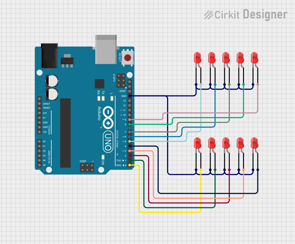
Example Circuit with Arduino UNO
Below is an example of how to connect and control the DC10YWA with an Arduino UNO:
Circuit Connections
- Connect Pin 11 (common cathode) to GND.
- Connect Pins 12-20 (anodes) to Arduino digital pins 2-10, each with a 220Ω resistor in series.
Arduino Code
// Example code to control the Kingbright DC10YWA 10-segment LED display
// using an Arduino UNO. Each segment is turned on sequentially.

const int segmentPins[10] = {2, 3, 4, 5, 6, 7, 8, 9, 10, 11}; // Anode pins

void setup() {
  // Set all segment pins as OUTPUT
  for (int i = 0; i < 10; i++) {
    pinMode(segmentPins[i], OUTPUT);
    digitalWrite(segmentPins[i], LOW); // Ensure all segments are off initially
  }
}

void loop() {
  // Sequentially light up each segment
  for (int i = 0; i < 10; i++) {
    digitalWrite(segmentPins[i], HIGH); // Turn on the segment
    delay(200); // Wait for 200ms
    digitalWrite(segmentPins[i], LOW);  // Turn off the segment
  }
}
Important Considerations and Best Practices
- Resistor Selection: Always use appropriate current-limiting resistors to protect the LEDs from overcurrent.
- Power Supply: Ensure the power supply can handle the total current draw of all active segments.
- Heat Dissipation: Avoid driving all segments at maximum current for extended periods to prevent overheating.
- Polarity: Double-check the polarity of the connections to avoid damaging the LEDs.
Troubleshooting and FAQs
Common Issues and Solutions
Segments Not Lighting Up
- Cause: Incorrect wiring or missing current-limiting resistors.
- Solution: Verify the connections and ensure resistors are in place.
Dim or Uneven Brightness
- Cause: Insufficient current or mismatched resistors.
- Solution: Use resistors of the same value for all segments and ensure the power supply is adequate.
Overheating
- Cause: Excessive current through the LEDs.
- Solution: Check resistor values and reduce the current to within the specified limits.
Flickering Segments
- Cause: Unstable power supply or loose connections.
- Solution: Secure all connections and use a stable power source.
FAQs
Q: Can I use the DC10YWA with a 3.3V microcontroller?
A: Yes, but ensure the forward voltage of 2.0V is met and use appropriate resistors to limit the current.
Q: Can I control the display using a shift register?
A: Yes, shift registers like the 74HC595 can be used to control the segments, reducing the number of GPIO pins required.
Q: Is the DC10YWA available in other colors?
A: Yes, Kingbright offers similar 10-segment displays in green, yellow, and other colors.
By following this documentation, you can effectively integrate the Kingbright DC10YWA 10-segment LED display into your projects.