How to Use USB to RS485: Examples, Pinouts, and Specs
Introduction
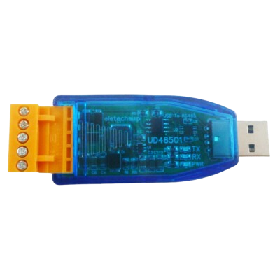
The USB to RS485 converter, manufactured by RS485 with part ID USB, is a versatile device that bridges USB-enabled systems with RS485 serial communication devices. It enables seamless data transmission over long distances and in electrically noisy environments, making it ideal for industrial automation, building management systems, and other applications requiring robust serial communication.
Explore Projects Built with USB to RS485


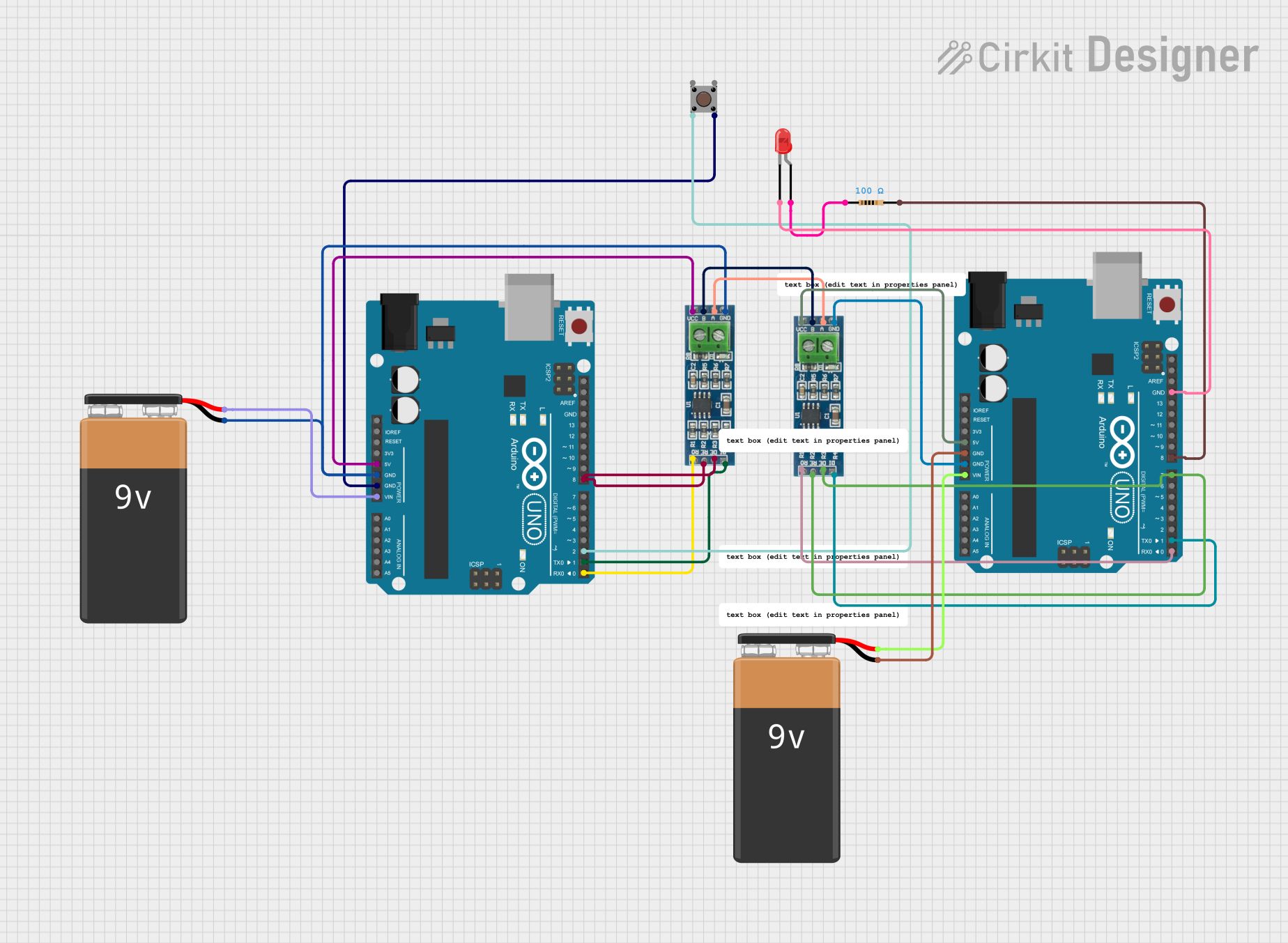
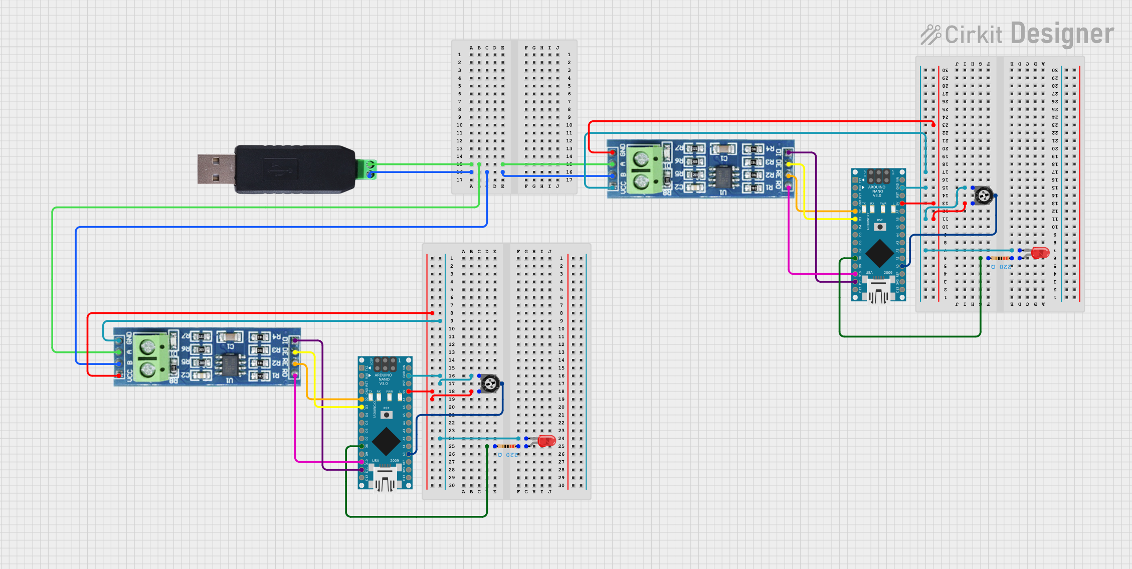
Explore Projects Built with USB to RS485
Common Applications and Use Cases
- Industrial automation and control systems
- Building management systems (e.g., HVAC, lighting control)
- Data acquisition systems
- Communication with RS485-enabled devices such as PLCs, sensors, and motor controllers
- Long-distance serial communication (up to 1200 meters)
Technical Specifications
Key Technical Details
| Parameter | Value |
|---|---|
| Communication Standard | RS485 |
| USB Interface | USB 2.0 (compatible with USB 1.1 and 3.0) |
| Baud Rate | 300 bps to 3 Mbps |
| Operating Voltage | 5V (via USB port) |
| Power Consumption | < 100 mA |
| Operating Temperature | -40°C to 85°C |
| Cable Length (typical) | 1 meter (USB cable) |
| RS485 Communication Range | Up to 1200 meters |
| Driver Support | Windows, macOS, Linux |
Pin Configuration and Descriptions
The USB to RS485 converter typically has the following pinouts for the RS485 interface:
| Pin Name | Description |
|---|---|
| A (D+) | RS485 Data Line Positive (non-inverting) |
| B (D-) | RS485 Data Line Negative (inverting) |
| GND | Ground Reference |
Usage Instructions
How to Use the Component in a Circuit
- Connect the USB Port: Plug the USB connector into your computer or USB host device. Ensure the appropriate drivers are installed (if required).
- Connect RS485 Lines:
- Connect the
A (D+)pin of the converter to theAline of the RS485 device. - Connect the
B (D-)pin of the converter to theBline of the RS485 device. - Optionally, connect the
GNDpin to the ground of the RS485 device for a common reference.
- Connect the
- Install Drivers: If the operating system does not automatically recognize the device, download and install the appropriate drivers from the manufacturer's website.
- Configure Communication Settings: Set the baud rate, parity, stop bits, and other parameters in your software to match the RS485 device's settings.
- Test Communication: Use terminal software or a custom application to send and receive data between the USB host and the RS485 device.
Important Considerations and Best Practices
- Termination Resistors: For long-distance communication, use a 120-ohm termination resistor across the
AandBlines at both ends of the RS485 bus to prevent signal reflections. - Biasing Resistors: Ensure proper biasing of the RS485 bus to maintain a known idle state when no devices are transmitting.
- Grounding: Connect the ground of the USB to RS485 converter to the ground of the RS485 device to avoid potential communication issues caused by ground loops.
- Device Addressing: If multiple devices are connected to the RS485 bus, ensure each device has a unique address.
Example Code for Arduino UNO
The USB to RS485 converter can be used with an Arduino UNO to communicate with RS485 devices. Below is an example code snippet:
#include <SoftwareSerial.h>

// Define RS485 communication pins
#define RX_PIN 10  // Arduino pin connected to RS485 RX
#define TX_PIN 11  // Arduino pin connected to RS485 TX
#define DE_PIN 9   // Arduino pin for Driver Enable (DE) control

// Initialize SoftwareSerial for RS485 communication
SoftwareSerial rs485Serial(RX_PIN, TX_PIN);

void setup() {
  pinMode(DE_PIN, OUTPUT);  // Set DE pin as output
  digitalWrite(DE_PIN, LOW); // Set DE to LOW (receive mode)

  rs485Serial.begin(9600);  // Start RS485 communication at 9600 baud
  Serial.begin(9600);       // Start Serial Monitor communication

  Serial.println("RS485 Communication Initialized");
}

void loop() {
  // Send data to RS485 device
  digitalWrite(DE_PIN, HIGH); // Enable transmit mode
  rs485Serial.println("Hello RS485 Device!");
  digitalWrite(DE_PIN, LOW);  // Enable receive mode

  delay(1000); // Wait for 1 second

  // Receive data from RS485 device
  if (rs485Serial.available()) {
    String receivedData = rs485Serial.readString();
    Serial.print("Received: ");
    Serial.println(receivedData);
  }
}
Notes:
- Connect the
DE_PINto the Driver Enable (DE) pin of the RS485 transceiver on the Arduino side. - Adjust the baud rate and communication parameters as needed to match the RS485 device.
Troubleshooting and FAQs
Common Issues and Solutions
Device Not Recognized by Computer:
- Ensure the USB cable is properly connected.
- Install the correct drivers for the USB to RS485 converter.
- Try a different USB port or computer.
No Communication with RS485 Device:
- Verify the
AandBlines are correctly connected. - Check the baud rate and other communication settings.
- Ensure termination resistors are installed if required.
- Verify the
Data Corruption or Noise:
- Use shielded cables for RS485 communication in noisy environments.
- Verify proper grounding between devices.
- Check for loose or damaged connections.
Multiple Devices Not Responding:
- Ensure each device on the RS485 bus has a unique address.
- Verify the total cable length and number of devices do not exceed RS485 specifications.
FAQs
Q: Can I use this converter with a Raspberry Pi?
A: Yes, the USB to RS485 converter is compatible with Raspberry Pi. Simply connect it to a USB port and configure the serial communication settings in your software.
Q: What is the maximum number of devices I can connect to the RS485 bus?
A: RS485 supports up to 32 devices on a single bus. For more devices, use RS485 repeaters.
Q: Do I need external power for the converter?
A: No, the converter is powered directly through the USB port.
Q: Can I use this converter for RS232 devices?
A: No, RS485 and RS232 are different communication standards. Use an RS232 to USB converter for RS232 devices.