How to Use DHT20: Examples, Pinouts, and Specs
Introduction
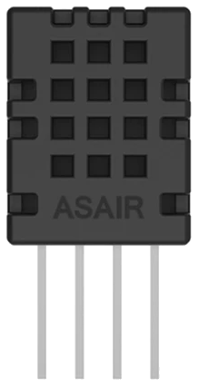
The DHT20 is a digital temperature and humidity sensor that provides accurate and reliable readings of environmental conditions. It integrates a capacitive humidity sensor and a thermistor to measure relative humidity and temperature, respectively. The DHT20 communicates via a digital I²C interface, making it easy to integrate into microcontroller-based systems. Its compact size and low power consumption make it ideal for a wide range of applications.
Explore Projects Built with DHT20
Explore Projects Built with DHT20
Common Applications and Use Cases
- Weather monitoring stations
- HVAC (Heating, Ventilation, and Air Conditioning) systems
- IoT (Internet of Things) devices
- Greenhouse monitoring
- Home automation systems
- Industrial environmental monitoring
Technical Specifications
The DHT20 sensor is designed for precision and ease of use. Below are its key technical details:
| Parameter | Value |
|---|---|
| Supply Voltage (VDD) | 2.2V to 5.5V |
| Operating Current | 0.4 mA (average) |
| Standby Current | ≤ 0.5 µA |
| Humidity Range | 0% to 100% RH |
| Humidity Accuracy | ±3% RH (typical) |
| Temperature Range | -40°C to 80°C |
| Temperature Accuracy | ±0.5°C (typical) |
| Communication Interface | I²C |
| I²C Address | 0x38 |
| Response Time | ≤ 1 second |
| Dimensions | 10mm x 10mm x 3.2mm |
Pin Configuration and Descriptions
The DHT20 has four pins, as described in the table below:
| Pin Number | Pin Name | Description |
|---|---|---|
| 1 | VDD | Power supply (2.2V to 5.5V) |
| 2 | SDA | Serial Data Line for I²C communication |
| 3 | GND | Ground |
| 4 | SCL | Serial Clock Line for I²C communication |
Usage Instructions
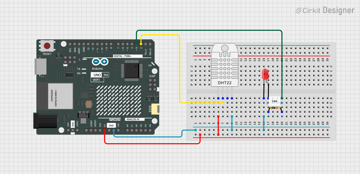
How to Use the DHT20 in a Circuit
- Power Supply: Connect the VDD pin to a 3.3V or 5V power source and the GND pin to ground.
- I²C Communication: Connect the SDA and SCL pins to the corresponding I²C pins on your microcontroller. Use pull-up resistors (typically 4.7kΩ) on both SDA and SCL lines if not already present on your board.
- Initialization: Ensure your microcontroller initializes the I²C bus and communicates with the DHT20 using its default address (0x38).
- Data Reading: Send the appropriate I²C commands to read temperature and humidity data from the sensor.
Important Considerations and Best Practices
- Power Stability: Ensure a stable power supply to avoid inaccurate readings.
- Placement: Avoid placing the sensor near heat sources or in direct sunlight, as this may affect temperature readings.
- Pull-Up Resistors: Verify that pull-up resistors are present on the SDA and SCL lines for proper I²C communication.
- Startup Time: Allow the sensor to stabilize for at least 2 seconds after power-up before taking readings.
- Data Polling: Avoid polling the sensor too frequently; a 1-second interval is recommended.
Example Code for Arduino UNO
Below is an example of how to use the DHT20 with an Arduino UNO:
#include <Wire.h> // Include the Wire library for I²C communication

#define DHT20_I2C_ADDRESS 0x38 // Default I²C address of the DHT20

void setup() {
  Serial.begin(9600); // Initialize serial communication for debugging
  Wire.begin();       // Initialize I²C communication
  delay(2000);        // Allow the sensor to stabilize after power-up
}

void loop() {
  // Request data from the DHT20
  Wire.beginTransmission(DHT20_I2C_ADDRESS);
  Wire.write(0xAC); // Command to trigger a measurement
  Wire.write(0x33); // Fixed command byte
  Wire.write(0x00); // Fixed command byte
  Wire.endTransmission();
  delay(80); // Wait for the measurement to complete

  // Read 7 bytes of data from the DHT20
  Wire.requestFrom(DHT20_I2C_ADDRESS, 7);
  if (Wire.available() == 7) {
    uint8_t data[7];
    for (int i = 0; i < 7; i++) {
      data[i] = Wire.read();
    }

    // Extract temperature and humidity data
    uint32_t rawHumidity = ((uint32_t)data[1] << 12) | ((uint32_t)data[2] << 4) |
                           ((data[3] & 0xF0) >> 4);
    uint32_t rawTemperature = (((uint32_t)data[3] & 0x0F) << 16) |
                              ((uint32_t)data[4] << 8) | data[5];

    float humidity = rawHumidity / 1048576.0 * 100.0; // Convert to %RH
    float temperature = rawTemperature / 1048576.0 * 200.0 - 50.0; // Convert to °C

    // Print the results
    Serial.print("Humidity: ");
    Serial.print(humidity);
    Serial.println(" %RH");
    Serial.print("Temperature: ");
    Serial.print(temperature);
    Serial.println(" °C");
  } else {
    Serial.println("Failed to read data from DHT20");
  }

  delay(1000); // Wait 1 second before the next reading
}
Troubleshooting and FAQs
Common Issues and Solutions
No Data from the Sensor:
- Ensure the sensor is powered correctly and the I²C connections (SDA, SCL) are secure.
- Verify that the correct I²C address (0x38) is being used in your code.
- Check for the presence of pull-up resistors on the SDA and SCL lines.
Inaccurate Readings:
- Ensure the sensor is not exposed to extreme environmental conditions (e.g., direct sunlight, high humidity).
- Allow the sensor to stabilize for at least 2 seconds after power-up.
I²C Communication Errors:
- Check the I²C bus speed; the DHT20 supports standard (100 kHz) and fast (400 kHz) modes.
- Ensure there are no conflicting devices on the I²C bus.
FAQs
Q: Can the DHT20 be used with a 5V microcontroller?
A: Yes, the DHT20 supports a supply voltage range of 2.2V to 5.5V, making it compatible with both 3.3V and 5V systems.
Q: How often can I read data from the DHT20?
A: It is recommended to read data no more frequently than once per second to ensure accurate measurements.
Q: Do I need to calibrate the DHT20?
A: No, the DHT20 is factory-calibrated and does not require additional calibration.