How to Use LR1824 Dual RX V1.0: Examples, Pinouts, and Specs
Introduction
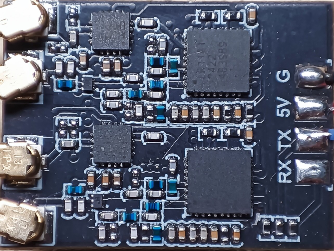
The LR1824 Dual RX V1.0, manufactured by HeppyModel (Part ID: RX_LR1121_Gemeni), is a dual-channel receiver module designed for wireless communication applications. It is capable of receiving signals from multiple transmitters, making it ideal for remote control systems, telemetry, and other wireless data transmission tasks. The module operates within a specific frequency range and offers reliable performance in environments requiring robust wireless communication.
Explore Projects Built with LR1824 Dual RX V1.0


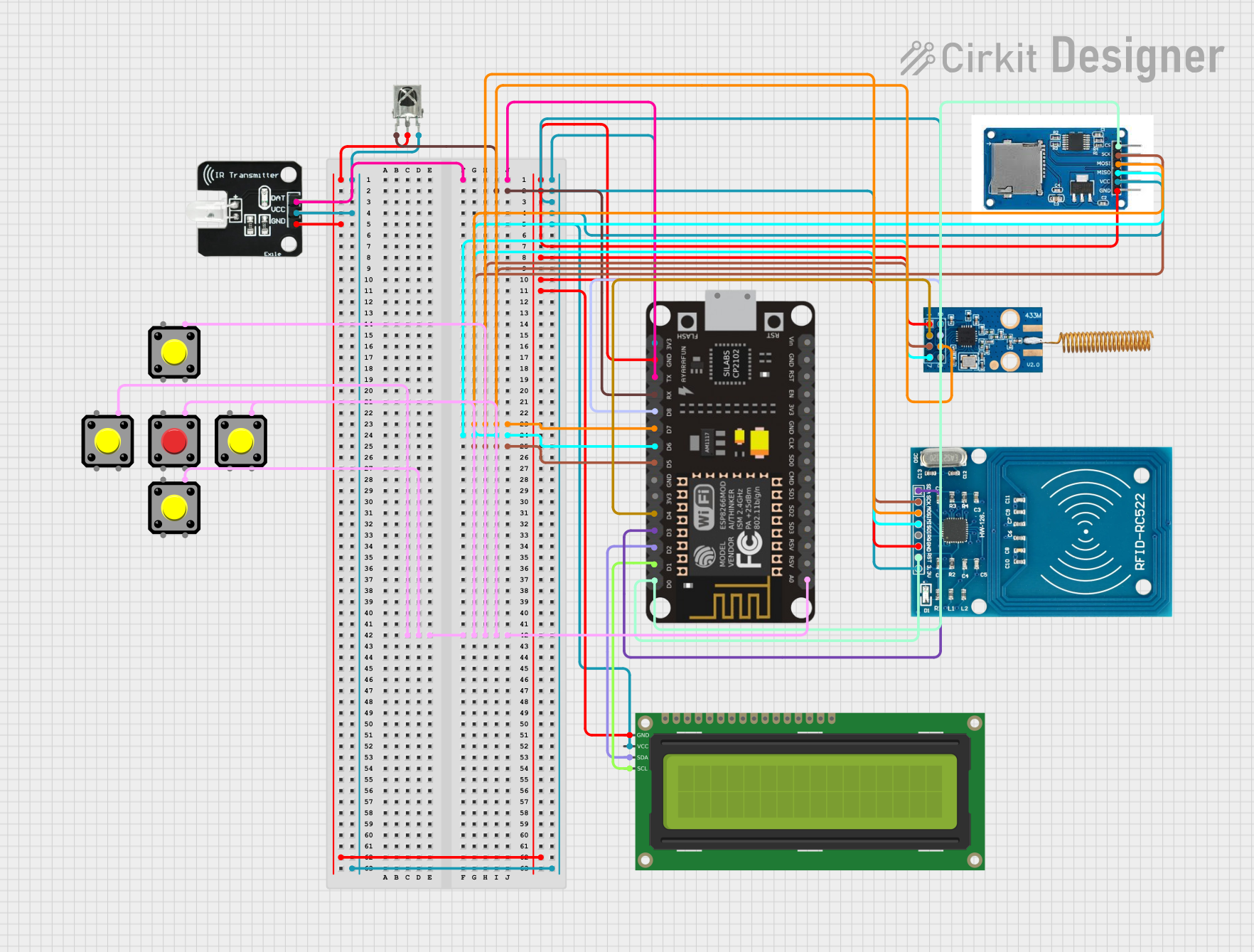
Explore Projects Built with LR1824 Dual RX V1.0
Common Applications
- Remote control systems for drones, RC cars, and boats
- Wireless telemetry for IoT devices
- Data transmission in industrial automation
- Wireless sensor networks
- Home automation systems
Technical Specifications
Key Technical Details
| Parameter | Value |
|---|---|
| Operating Voltage | 3.3V - 5.5V |
| Operating Frequency | 2.4 GHz |
| Number of Channels | 2 |
| Sensitivity | -105 dBm |
| Data Rate | Up to 1 Mbps |
| Communication Protocol | Proprietary (HeppyModel) |
| Dimensions | 25mm x 15mm x 5mm |
| Operating Temperature | -20°C to 70°C |
| Antenna Interface | U.FL Connector |
Pin Configuration and Descriptions
The LR1824 Dual RX V1.0 module has a total of 8 pins. Below is the pinout and description:
| Pin Number | Pin Name | Description |
|---|---|---|
| 1 | VCC | Power supply input (3.3V - 5.5V) |
| 2 | GND | Ground connection |
| 3 | RX1 | Data output for Channel 1 |
| 4 | RX2 | Data output for Channel 2 |
| 5 | CONFIG | Configuration pin for setting operating modes |
| 6 | STATUS | Status indicator output (e.g., signal strength) |
| 7 | ANT | Antenna connection (U.FL interface) |
| 8 | RESET | Reset pin to restart the module |
Usage Instructions
How to Use the LR1824 Dual RX V1.0 in a Circuit
- Power Supply: Connect the VCC pin to a regulated power source (3.3V to 5.5V) and the GND pin to the ground of your circuit.
- Antenna Connection: Attach a compatible U.FL antenna to the ANT pin for optimal signal reception.
- Data Outputs: Use the RX1 and RX2 pins to receive data from the two channels. These pins output digital signals that can be processed by a microcontroller or other devices.
- Configuration: Use the CONFIG pin to set the module's operating mode. Refer to the manufacturer's datasheet for specific configuration options.
- Reset: If needed, connect the RESET pin to a microcontroller or a push-button to restart the module.
Important Considerations and Best Practices
- Ensure the power supply is stable and within the specified voltage range to avoid damage to the module.
- Use a high-quality U.FL antenna to maximize signal reception and range.
- Keep the module away from sources of electromagnetic interference (EMI) to maintain signal integrity.
- If using the module with a microcontroller, ensure the microcontroller's logic levels are compatible with the module's output.
Example: Connecting to an Arduino UNO
Below is an example of how to connect the LR1824 Dual RX V1.0 to an Arduino UNO and read data from the RX1 and RX2 pins.
Circuit Connections
- VCC: Connect to the 5V pin on the Arduino.
- GND: Connect to the GND pin on the Arduino.
- RX1: Connect to Arduino digital pin 2.
- RX2: Connect to Arduino digital pin 3.
- RESET: Connect to Arduino digital pin 4 (optional).
Arduino Code Example
// Define pins for the LR1824 Dual RX V1.0
const int rx1Pin = 2;  // RX1 data output connected to digital pin 2
const int rx2Pin = 3;  // RX2 data output connected to digital pin 3
const int resetPin = 4; // Reset pin connected to digital pin 4 (optional)

void setup() {
  // Initialize serial communication for debugging
  Serial.begin(9600);

  // Set pin modes
  pinMode(rx1Pin, INPUT);
  pinMode(rx2Pin, INPUT);
  pinMode(resetPin, OUTPUT);

  // Reset the module (optional)
  digitalWrite(resetPin, LOW);
  delay(100); // Hold reset for 100ms
  digitalWrite(resetPin, HIGH);
}

void loop() {
  // Read data from RX1 and RX2
  int rx1Data = digitalRead(rx1Pin);
  int rx2Data = digitalRead(rx2Pin);

  // Print the received data to the Serial Monitor
  Serial.print("RX1: ");
  Serial.print(rx1Data);
  Serial.print(" | RX2: ");
  Serial.println(rx2Data);

  delay(100); // Small delay for readability
}
Troubleshooting and FAQs
Common Issues and Solutions
No Signal Reception
- Cause: Antenna not connected or improperly connected.
- Solution: Ensure the U.FL antenna is securely attached to the ANT pin.
Intermittent Data Loss
- Cause: Electromagnetic interference or poor power supply.
- Solution: Move the module away from EMI sources and use a stable power supply.
Module Not Responding
- Cause: Incorrect wiring or configuration.
- Solution: Double-check all connections and ensure the CONFIG pin is set correctly.
Weak Signal Strength
- Cause: Obstructions or low-quality antenna.
- Solution: Use a high-gain antenna and ensure a clear line of sight between the transmitter and receiver.
FAQs
Q: Can the LR1824 Dual RX V1.0 operate on 3.3V?
A: Yes, the module supports an operating voltage range of 3.3V to 5.5V.
Q: What is the maximum range of the module?
A: The range depends on the antenna and environment but typically extends up to 100 meters in open space.
Q: Can I use this module with a Raspberry Pi?
A: Yes, the module can be interfaced with a Raspberry Pi, provided the GPIO pins are configured correctly.
Q: Is the module compatible with standard communication protocols like SPI or I2C?
A: No, the module uses a proprietary communication protocol developed by HeppyModel.
Q: How do I update the firmware of the module?
A: Firmware updates, if available, can be performed using the manufacturer's recommended tools and procedures. Refer to the official documentation for details.