
How to Use LPC2103: Examples, Pinouts, and Specs
 Design with LPC2103 in Cirkit Designer
Introduction
The LPC2103 is a low-power, high-performance microcontroller developed by NXP. It is based on the ARM7TDMI-S core, which provides a 32-bit architecture optimized for embedded applications. With up to 58 KB of on-chip flash memory, 8 KB of SRAM, and a variety of peripherals such as GPIO, UART, SPI, and timers, the LPC2103 is well-suited for applications requiring efficient processing and flexible interfacing.
Explore Projects Built with LPC2103
 Open Project in Cirkit Designer
 Open Project in Cirkit Designer
 Open Project in Cirkit Designer
 Open Project in Cirkit Designer
Explore Projects Built with LPC2103
Open Project in Cirkit DesignerOpen Project in Cirkit DesignerOpen Project in Cirkit DesignerOpen Project in Cirkit DesignerCommon Applications
- Industrial automation and control systems
- Consumer electronics
- Data acquisition systems
- Embedded systems requiring low power and high performance
- Communication devices
Technical Specifications
Key Technical Details
| Parameter | Specification |
|---|---|
| Core Architecture | ARM7TDMI-S |
| Operating Voltage | 3.0V to 3.6V |
| Flash Memory | Up to 58 KB |
| SRAM | 8 KB |
| Clock Speed | Up to 70 MHz |
| GPIO Pins | Up to 46 |
| Communication Interfaces | UART, SPI, I2C |
| Timers | 2 x 32-bit timers |
| ADC | Not available |
| Power Consumption | Low power, suitable for battery use |
| Package | LQFP48 |
Pin Configuration and Descriptions
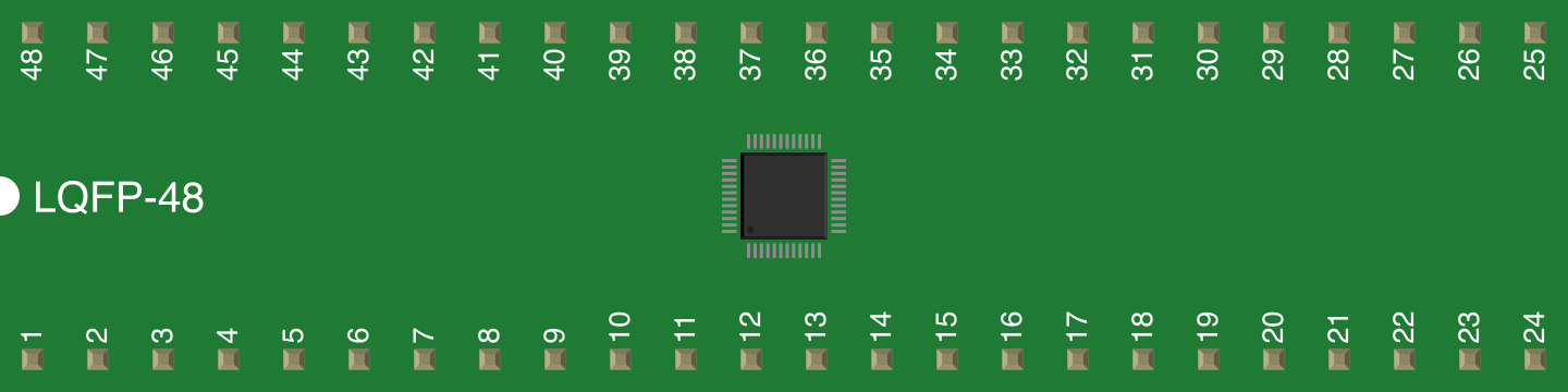
The LPC2103 is available in a 48-pin LQFP package. Below is a summary of key pins and their functions:
| Pin Number | Pin Name | Function Description |
|---|---|---|
| 1 | VSS | Ground |
| 2 | VDD | Power supply (3.3V) |
| 10 | P0.0/TXD0 | GPIO, UART0 Transmit |
| 11 | P0.1/RXD0 | GPIO, UART0 Receive |
| 15 | P0.8/SCL | GPIO, I2C Clock Line |
| 16 | P0.9/SDA | GPIO, I2C Data Line |
| 20 | P0.15 | GPIO |
| 30 | XTAL1 | External oscillator input |
| 31 | XTAL2 | External oscillator output |
| 40 | RESET | Reset input (active low) |
| 48 | P1.31 | GPIO |
For a complete pinout, refer to the LPC2103 datasheet provided by NXP.
Usage Instructions
Using the LPC2103 in a Circuit
- Power Supply: Connect the VDD pin to a 3.3V regulated power supply and the VSS pin to ground.
- Clock Configuration: Use an external crystal oscillator (e.g., 12 MHz) connected to XTAL1 and XTAL2 for stable clock operation.
- Reset Circuit: Connect a pull-up resistor (e.g., 10 kΩ) to the RESET pin to ensure proper startup.
- Programming Interface: Use UART0 (TXD0 and RXD0) for programming and debugging. A USB-to-UART converter can be used for interfacing with a PC.
- GPIO Usage: Configure GPIO pins as input or output in software. Ensure proper pull-up or pull-down resistors are used if required.
Important Considerations
- Voltage Levels: Ensure all input signals are within the 3.3V logic level range to avoid damage.
- Decoupling Capacitors: Place 0.1 µF decoupling capacitors close to the VDD pin to reduce noise.
- Programming Tools: Use NXP's Flash Magic software or similar tools for programming the LPC2103.
- Debugging: The JTAG interface can be used for in-circuit debugging.
Example: Interfacing LPC2103 with Arduino UNO
The LPC2103 can communicate with an Arduino UNO via UART. Below is an example Arduino sketch to send data to the LPC2103:
// Arduino UNO UART Communication with LPC2103
// Sends "Hello LPC2103" to the LPC2103 via UART

void setup() {
  Serial.begin(9600); // Initialize UART at 9600 baud rate
}

void loop() {
  Serial.println("Hello LPC2103"); // Send data to LPC2103
  delay(1000); // Wait for 1 second
}
On the LPC2103 side, configure UART0 to receive data and process it accordingly.
Troubleshooting and FAQs
Common Issues and Solutions
Microcontroller Not Responding
- Cause: Incorrect power supply or reset circuit.
- Solution: Verify the power supply voltage (3.3V) and ensure the RESET pin is properly connected with a pull-up resistor.
UART Communication Fails
- Cause: Baud rate mismatch or incorrect wiring.
- Solution: Ensure the baud rate is the same on both devices and check TXD/RXD connections.
Program Not Running After Power Cycle
- Cause: Incorrect bootloader configuration.
- Solution: Verify the bootloader settings and ensure the program is flashed correctly.
Excessive Power Consumption
- Cause: Unused peripherals not disabled.
- Solution: Disable unused peripherals in software to reduce power consumption.
FAQs
Q: Can the LPC2103 operate at 5V?
A: No, the LPC2103 operates at a voltage range of 3.0V to 3.6V. Exceeding this range may damage the device.
Q: Does the LPC2103 have an ADC?
A: No, the LPC2103 does not include an ADC. For applications requiring analog-to-digital conversion, an external ADC module is needed.
Q: How do I program the LPC2103?
A: The LPC2103 can be programmed via UART0 using tools like Flash Magic. Alternatively, the JTAG interface can be used for programming and debugging.
Q: What is the maximum clock speed of the LPC2103?
A: The LPC2103 can operate at a maximum clock speed of 70 MHz.
For further details, refer to the official NXP LPC2103 datasheet and user manual.