Cirkit Designer
Your all-in-one circuit design IDE
Home /
Component Documentation
How to Use rtc MODULE: Examples, Pinouts, and Specs
Introduction
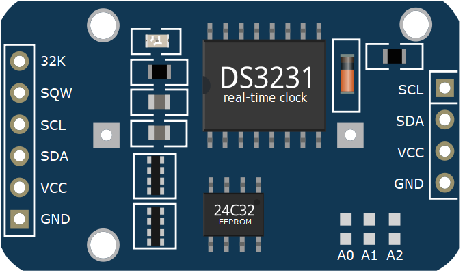
A Real-Time Clock (RTC) Module is an electronic component that maintains an accurate track of the current time and date. It is commonly used in applications such as data loggers, clocks, servers, and other systems where timekeeping is crucial. The RTC module typically includes a quartz crystal and a battery to keep the time updated even when the main power is off.
Explore Projects Built with rtc MODULE
NodeMCU ESP8266 Based Smart Relay with LCD Interface and RTC Support
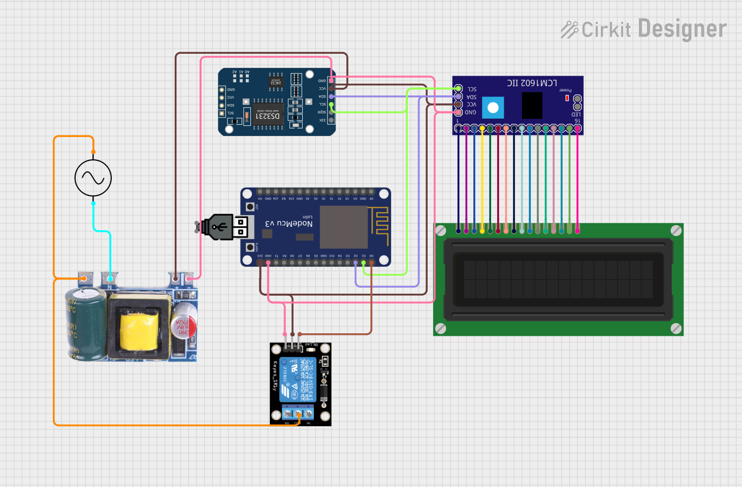
This circuit features a NodeMCU V3 ESP8266 microcontroller connected to a KY-019 Relay module for controlling power to a device, a DS3231 Real Time Clock (RTC) for timekeeping, and an LCM1602 IIC module interfaced with an LCD Display for user interface. The circuit is powered by a Mini AC-DC converter module that steps down AC mains to 5V, and the NodeMCU facilitates communication between the RTC, the relay, and the display, likely for scheduling and displaying the status of the connected device.
Arduino UNO Controlled Relay with DS3231 RTC

This circuit features an Arduino UNO microcontroller connected to a DS3231 Real Time Clock (RTC) module and a 12V single-channel relay. The Arduino provides power to both the RTC and the relay, and it communicates with the RTC via I2C using the SDA and SCL lines connected to A4 and A5 respectively. The relay is controlled by the Arduino through a digital output on pin D13, allowing the Arduino to switch external loads on and off based on time events managed by the RTC.
Arduino UNO Controlled Servo with DS1307 Real-Time Clock
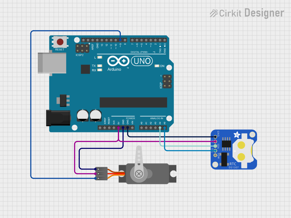
This circuit consists of an Arduino UNO microcontroller connected to a DS1307 Real Time Clock (RTC) module and a servo motor. The RTC module communicates with the Arduino via the I2C protocol using SDA and SCL lines, while the servo is controlled by a PWM signal from the Arduino. The circuit is designed to use the precise timekeeping of the RTC to schedule and execute movements with the servo motor.
Dual RTC DS3231 Synchronization with Glyph C3 Microcontroller

This circuit integrates two RTC DS3231 real-time clock modules with a Glyph C3 microcontroller. The RTC modules are connected to the microcontroller via I2C communication protocol, using the SCL and SDA lines for clock and data respectively. Both RTC modules and the microcontroller share a common power supply (3V3) and ground (GND), indicating that they operate at the same voltage level.
Explore Projects Built with rtc MODULE
NodeMCU ESP8266 Based Smart Relay with LCD Interface and RTC Support
This circuit features a NodeMCU V3 ESP8266 microcontroller connected to a KY-019 Relay module for controlling power to a device, a DS3231 Real Time Clock (RTC) for timekeeping, and an LCM1602 IIC module interfaced with an LCD Display for user interface. The circuit is powered by a Mini AC-DC converter module that steps down AC mains to 5V, and the NodeMCU facilitates communication between the RTC, the relay, and the display, likely for scheduling and displaying the status of the connected device.
Arduino UNO Controlled Relay with DS3231 RTC
This circuit features an Arduino UNO microcontroller connected to a DS3231 Real Time Clock (RTC) module and a 12V single-channel relay. The Arduino provides power to both the RTC and the relay, and it communicates with the RTC via I2C using the SDA and SCL lines connected to A4 and A5 respectively. The relay is controlled by the Arduino through a digital output on pin D13, allowing the Arduino to switch external loads on and off based on time events managed by the RTC.
Arduino UNO Controlled Servo with DS1307 Real-Time Clock
This circuit consists of an Arduino UNO microcontroller connected to a DS1307 Real Time Clock (RTC) module and a servo motor. The RTC module communicates with the Arduino via the I2C protocol using SDA and SCL lines, while the servo is controlled by a PWM signal from the Arduino. The circuit is designed to use the precise timekeeping of the RTC to schedule and execute movements with the servo motor.
Dual RTC DS3231 Synchronization with Glyph C3 Microcontroller
This circuit integrates two RTC DS3231 real-time clock modules with a Glyph C3 microcontroller. The RTC modules are connected to the microcontroller via I2C communication protocol, using the SCL and SDA lines for clock and data respectively. Both RTC modules and the microcontroller share a common power supply (3V3) and ground (GND), indicating that they operate at the same voltage level.
Common Applications and Use Cases
- Data logging with time stamps
- Time-based control systems
- Clocks and watches
- Maintaining system time for computers and embedded systems
- IoT devices requiring scheduled tasks
Technical Specifications
Key Technical Details
- Voltage: Typically 3.3V to 5V
- Current: Battery backup current in the range of 1µA to 5µA
- Time Accuracy: ±1 to 5 ppm depending on the model
- Battery: Coin cell (e.g., CR2032) for backup power
Pin Configuration and Descriptions
| Pin Number | Name | Description |
|---|---|---|
| 1 | VCC | Connect to 3.3V or 5V power supply |
| 2 | GND | Connect to ground |
| 3 | SDA | Serial Data Line for I2C communication |
| 4 | SCL | Serial Clock Line for I2C communication |
| 5 | SQW | Square Wave/Output Driver (optional use) |
| 6 | 32K | 32kHz Output (optional use) |
| 7 | RST | Reset Pin (optional use) |
Usage Instructions
How to Use the RTC Module in a Circuit
- Powering the Module: Connect the VCC pin to a 3.3V or 5V power supply and the GND pin to the ground.
- Communication: Connect the SDA and SCL pins to the corresponding SDA and SCL pins on your microcontroller (e.g., Arduino).
- Backup Battery: Insert a coin cell battery into the battery holder to ensure the RTC can keep time when the main power is off.
Important Considerations and Best Practices
- Ensure that the power supply voltage matches the RTC module's requirements.
- Use pull-up resistors on the SDA and SCL lines if they are not included on the RTC module.
- Avoid exposing the RTC module to extreme temperatures to maintain time accuracy.
- When inserting the battery, ensure the correct polarity to avoid damaging the RTC module.
Example Code for Arduino UNO
#include <Wire.h>
#include "RTClib.h"

RTC_DS3231 rtc; // Replace with your specific RTC library and object

void setup() {
  Wire.begin();
  Serial.begin(9600);

  if (!rtc.begin()) {
    Serial.println("Couldn't find RTC");
    while (1);
  }

  if (rtc.lostPower()) {
    Serial.println("RTC lost power, let's set the time!");
    // The following line sets the RTC to the date & time this sketch was compiled
    rtc.adjust(DateTime(F(__DATE__), F(__TIME__)));
  }
}

void loop() {
  DateTime now = rtc.now();

  Serial.print(now.year(), DEC);
  Serial.print('/');
  Serial.print(now.month(), DEC);
  Serial.print('/');
  Serial.print(now.day(), DEC);
  Serial.print(" ");
  Serial.print(now.hour(), DEC);
  Serial.print(':');
  Serial.print(now.minute(), DEC);
  Serial.print(':');
  Serial.print(now.second(), DEC);
  Serial.println();

  delay(1000);
}
Troubleshooting and FAQs
Common Issues Users Might Face
- Time not updating: Ensure the battery is properly installed and has charge.
- Incorrect time after power cycle: Make sure the time is set correctly after initializing the RTC module.
- Communication errors: Check the wiring of SDA and SCL lines, and ensure pull-up resistors are in place if needed.
Solutions and Tips for Troubleshooting
- Battery Issues: Replace the battery if the RTC module fails to keep time after power loss.
- I2C Communication: Use an I2C scanner sketch to verify that the microcontroller can detect the RTC module.
- Resetting Time: Use the provided example code to reset the time when the RTC has lost power or is not keeping time correctly.
Remember to consult the datasheet of your specific RTC module for more detailed information and troubleshooting tips.