Cirkit Designer Logo
Cirkit Designer
Your all-in-one circuit design IDE
Home / 
Component Documentation

How to Use RX470C: Examples, Pinouts, and Specs
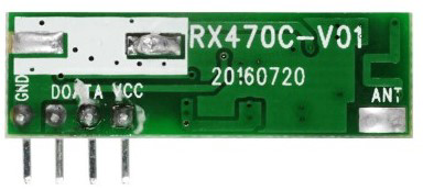
Image of RX470C
Cirkit Designer LogoDesign with RX470C in Cirkit Designer

Introduction

The RX470C is a high-performance graphics processing unit (GPU) designed to deliver exceptional gaming and graphics rendering capabilities. Built with advanced architecture, it ensures efficient processing and supports modern graphics APIs such as DirectX and OpenGL. The RX470C is optimized for power efficiency, making it an excellent choice for gaming enthusiasts, content creators, and professionals working with demanding graphical applications.

Explore Projects Built with RX470C

Use Cirkit Designer to design, explore, and prototype these projects online. Some projects support real-time simulation. Click "Open Project" to start designing instantly!
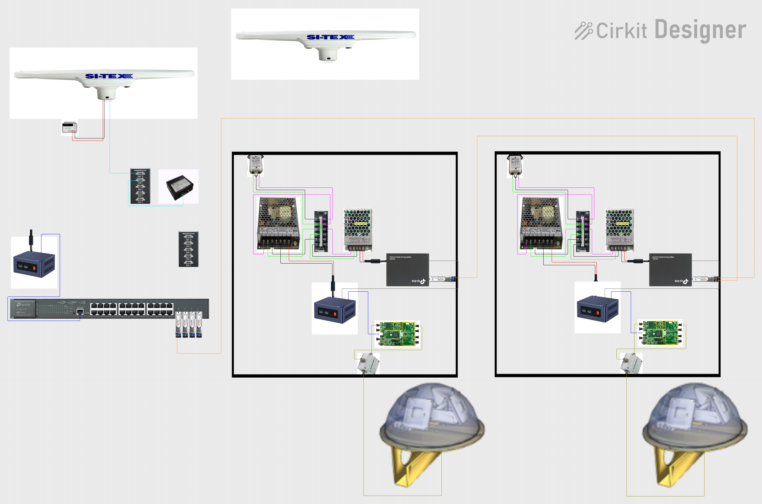
Satellite-Based Timing and Navigation System with SDR and Atomic Clock Synchronization
Image of GPS 시스템 측정 구성도_Confirm: A project utilizing RX470C in a practical application
This circuit appears to be a complex system involving power supply management, GPS and timing synchronization, and data communication. It includes a SI-TEX G1 Satellite Compass for GPS data, an XHTF1021 Atomic Rubidium Clock for precise timing, and Ettus USRP B200 units for software-defined radio communication. Power is supplied through various SMPS units and distributed via terminal blocks and DC jacks. Data communication is facilitated by Beelink MINI S12 N95 computers, RS232 splitters, and a 1000BASE-T Media Converter for network connectivity. RF Directional Couplers are used to interface antennas with the USRP units, and the entire system is likely contained within cases for protection and organization.
Cirkit Designer LogoOpen Project in Cirkit Designer
Satellite Compass and Network-Integrated GPS Data Processing System
Image of GPS 시스템 측정 구성도_241016: A project utilizing RX470C in a practical application
This circuit comprises a satellite compass, a mini PC, two GPS antennas, power supplies, a network switch, media converters, and an atomic rubidium clock. The satellite compass is powered by a triple output DC power supply and interfaces with an RS232 splitter for 1PPS signals. The mini PCs are connected to the USRP B200 devices via USB for data and power, and to media converters via Ethernet, which in turn connect to a network switch using fiber optic links. The antennas are connected to the USRP B200s through RF directional couplers, and the atomic clock provides a 1PPS input to the RS232 splitter.
Cirkit Designer LogoOpen Project in Cirkit Designer
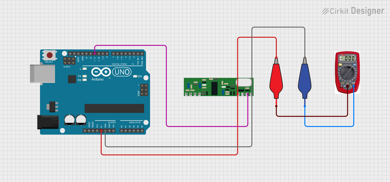
Arduino UNO with 433MHz RF Module for Wireless Communication
Image of Receiver: A project utilizing RX470C in a practical application
This circuit consists of an Arduino UNO connected to an RXN433MHz radio frequency module. The Arduino provides 5V power and ground to the RF module and is configured to communicate with it via digital pin D11. Additionally, a multimeter is connected with alligator clip cables to measure the voltage supplied to the RF module.
Cirkit Designer LogoOpen Project in Cirkit Designer
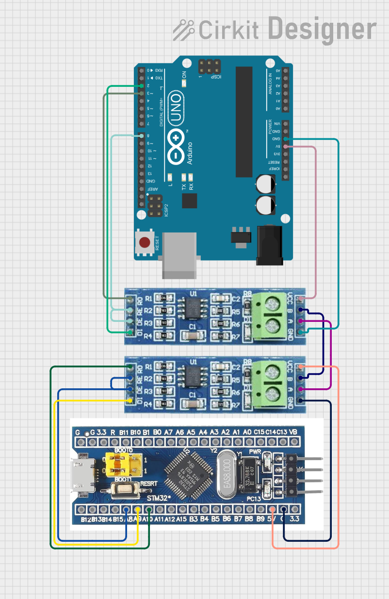
STM32 and Arduino UNO Based Dual RS485 Communication Interface
Image of STM to Arduino RS485: A project utilizing RX470C in a practical application
This circuit consists of two microcontrollers, an STM32F103C8T6 and an Arduino UNO, each interfaced with separate RS485 transceiver modules for serial communication. The STM32F103C8T6 controls the RE (Receiver Enable) and DE (Driver Enable) pins of one RS485 module to manage its operation, and communicates via the A9 and A10 pins for DI (Data Input) and RO (Receiver Output), respectively. The Arduino UNO is similarly connected to another RS485 module, with digital pins D2 and D3 interfacing with DI and RO, and D8 controlling both RE and DE. The RS485 modules are connected to each other through their A and B differential communication lines, enabling serial data exchange between the two microcontrollers over a robust and long-distance capable RS485 network.
Cirkit Designer LogoOpen Project in Cirkit Designer

Explore Projects Built with RX470C

Use Cirkit Designer to design, explore, and prototype these projects online. Some projects support real-time simulation. Click "Open Project" to start designing instantly!
Image of GPS 시스템 측정 구성도_Confirm: A project utilizing RX470C in a practical application
Satellite-Based Timing and Navigation System with SDR and Atomic Clock Synchronization
This circuit appears to be a complex system involving power supply management, GPS and timing synchronization, and data communication. It includes a SI-TEX G1 Satellite Compass for GPS data, an XHTF1021 Atomic Rubidium Clock for precise timing, and Ettus USRP B200 units for software-defined radio communication. Power is supplied through various SMPS units and distributed via terminal blocks and DC jacks. Data communication is facilitated by Beelink MINI S12 N95 computers, RS232 splitters, and a 1000BASE-T Media Converter for network connectivity. RF Directional Couplers are used to interface antennas with the USRP units, and the entire system is likely contained within cases for protection and organization.
Cirkit Designer LogoOpen Project in Cirkit Designer
Image of GPS 시스템 측정 구성도_241016: A project utilizing RX470C in a practical application
Satellite Compass and Network-Integrated GPS Data Processing System
This circuit comprises a satellite compass, a mini PC, two GPS antennas, power supplies, a network switch, media converters, and an atomic rubidium clock. The satellite compass is powered by a triple output DC power supply and interfaces with an RS232 splitter for 1PPS signals. The mini PCs are connected to the USRP B200 devices via USB for data and power, and to media converters via Ethernet, which in turn connect to a network switch using fiber optic links. The antennas are connected to the USRP B200s through RF directional couplers, and the atomic clock provides a 1PPS input to the RS232 splitter.
Cirkit Designer LogoOpen Project in Cirkit Designer
Image of Receiver: A project utilizing RX470C in a practical application
Arduino UNO with 433MHz RF Module for Wireless Communication
This circuit consists of an Arduino UNO connected to an RXN433MHz radio frequency module. The Arduino provides 5V power and ground to the RF module and is configured to communicate with it via digital pin D11. Additionally, a multimeter is connected with alligator clip cables to measure the voltage supplied to the RF module.
Cirkit Designer LogoOpen Project in Cirkit Designer
Image of STM to Arduino RS485: A project utilizing RX470C in a practical application
STM32 and Arduino UNO Based Dual RS485 Communication Interface
This circuit consists of two microcontrollers, an STM32F103C8T6 and an Arduino UNO, each interfaced with separate RS485 transceiver modules for serial communication. The STM32F103C8T6 controls the RE (Receiver Enable) and DE (Driver Enable) pins of one RS485 module to manage its operation, and communicates via the A9 and A10 pins for DI (Data Input) and RO (Receiver Output), respectively. The Arduino UNO is similarly connected to another RS485 module, with digital pins D2 and D3 interfacing with DI and RO, and D8 controlling both RE and DE. The RS485 modules are connected to each other through their A and B differential communication lines, enabling serial data exchange between the two microcontrollers over a robust and long-distance capable RS485 network.
Cirkit Designer LogoOpen Project in Cirkit Designer

Common Applications and Use Cases

  • High-performance gaming
  • 3D rendering and animation
  • Video editing and post-production
  • Virtual reality (VR) applications
  • Machine learning and AI model acceleration
  • Multi-monitor setups for productivity

Technical Specifications

The RX470C is engineered to provide a balance of performance and efficiency. Below are its key technical specifications:

General Specifications

Parameter Value
GPU Architecture Advanced GCN (Graphics Core Next)
Process Node 14nm FinFET
Base Clock Speed 926 MHz
Boost Clock Speed 1206 MHz
Memory Type GDDR5
Memory Capacity 4GB / 8GB
Memory Bandwidth 211 GB/s
TDP (Thermal Design Power) 120W
API Support DirectX 12, OpenGL 4.5, Vulkan
PCIe Interface PCIe 3.0 x16

Pin Configuration and Descriptions

The RX470C connects to the motherboard via the PCIe slot and requires additional power through a 6-pin PCIe power connector. Below is the pin configuration for the 6-pin power connector:

Pin Number Signal Name Description
1 +12V 12V power supply
2 +12V 12V power supply
3 +12V 12V power supply
4 Ground Ground connection
5 Ground Ground connection
6 Ground Ground connection

Usage Instructions

How to Use the RX470C in a System

  1. Install the GPU:
    • Insert the RX470C into the PCIe x16 slot on the motherboard.
    • Secure the GPU to the case using screws to prevent movement.
  2. Connect Power:
    • Attach the 6-pin PCIe power connector from the power supply to the GPU.
    • Ensure the power supply meets the minimum requirement of 450W.
  3. Install Drivers:
    • Download the latest drivers from the manufacturer's website.
    • Install the drivers to enable full functionality and performance.
  4. Configure Display:
    • Connect your monitor(s) to the GPU using HDMI, DisplayPort, or DVI.
    • Adjust display settings in the operating system or GPU control panel.

Important Considerations and Best Practices

  • Ensure proper airflow in the case to prevent overheating. Use additional case fans if necessary.
  • Regularly clean the GPU and its fans to avoid dust buildup.
  • Use a power supply with sufficient wattage and quality to ensure stable operation.
  • Update drivers periodically to benefit from performance improvements and bug fixes.

Example: Using RX470C with an Arduino UNO

While the RX470C is not directly compatible with an Arduino UNO, it can be used in projects where the Arduino communicates with a PC running the GPU. For example, you can use the Arduino to send commands to a PC application that utilizes the RX470C for rendering or computation.

Here is an example Arduino sketch to send serial commands to a PC:

// Arduino code to send commands to a PC for GPU processing
void setup() {
  Serial.begin(9600); // Initialize serial communication at 9600 baud
}

void loop() {
  Serial.println("Render Frame"); // Send a command to the PC
  delay(1000); // Wait for 1 second before sending the next command
}

On the PC side, you can write a program in Python or another language to receive these commands and utilize the RX470C for processing.

Troubleshooting and FAQs

Common Issues and Solutions

  1. No Display Output:

    • Ensure the GPU is properly seated in the PCIe slot.
    • Verify that the power connectors are securely attached.
    • Check the monitor connection and input source.
  2. Overheating:

    • Clean the GPU fans and heatsink to remove dust.
    • Improve case airflow by adding or repositioning fans.
    • Consider reapplying thermal paste if the GPU is old.
  3. Driver Installation Fails:

    • Uninstall any existing GPU drivers before installing new ones.
    • Download the correct driver version for your operating system.
    • Disable antivirus software temporarily during installation.
  4. System Crashes or Freezes:

    • Check if the power supply is sufficient for the GPU and other components.
    • Test the GPU in another system to rule out hardware issues.
    • Update the motherboard BIOS to the latest version.

FAQs

Q: Can the RX470C support 4K gaming?
A: Yes, the RX470C can handle 4K gaming, but performance may vary depending on the game and settings. For optimal performance, use medium to high settings.

Q: Does the RX470C support VR?
A: Yes, the RX470C is VR-ready and supports popular VR headsets.

Q: Can I overclock the RX470C?
A: Yes, the RX470C supports overclocking. Use the manufacturer's software or third-party tools to adjust clock speeds and monitor temperatures.

Q: What is the maximum number of monitors supported?
A: The RX470C can support up to four monitors simultaneously, depending on the available output ports.

Q: Is the RX470C compatible with Linux?
A: Yes, the RX470C is compatible with Linux. Ensure you install the appropriate drivers for your distribution.