
How to Use YDLIDAR X3: Examples, Pinouts, and Specs
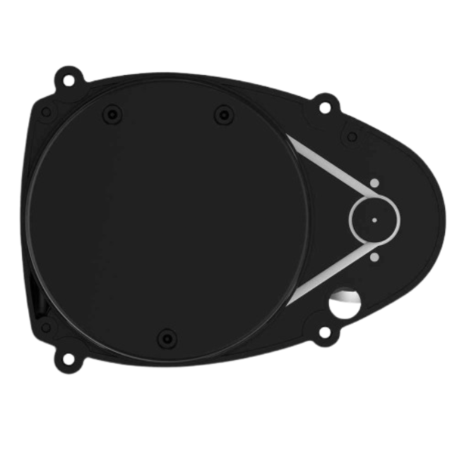
 Design with YDLIDAR X3 in Cirkit Designer
Introduction
The YDLIDAR X3, manufactured by Shenzhen EAI, is a 360-degree laser scanner designed for robotic and automation applications. It provides precise distance measurements and enables environmental mapping, making it an essential component for navigation, obstacle avoidance, and SLAM (Simultaneous Localization and Mapping) in robotics. With its compact design, high-speed data acquisition, and robust performance, the YDLIDAR X3 is suitable for both indoor and outdoor environments.
Explore Projects Built with YDLIDAR X3
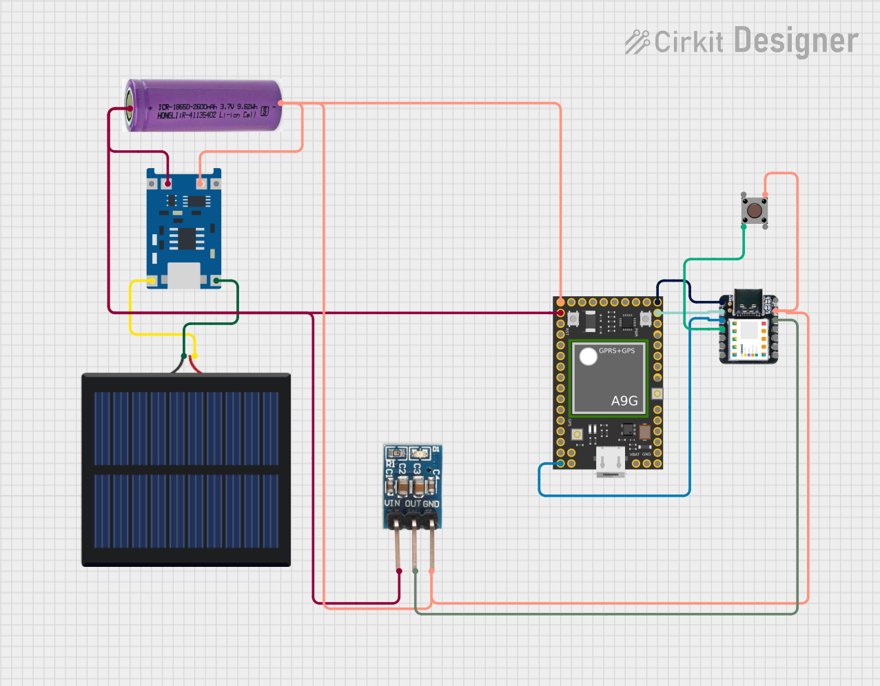 Open Project in Cirkit Designer
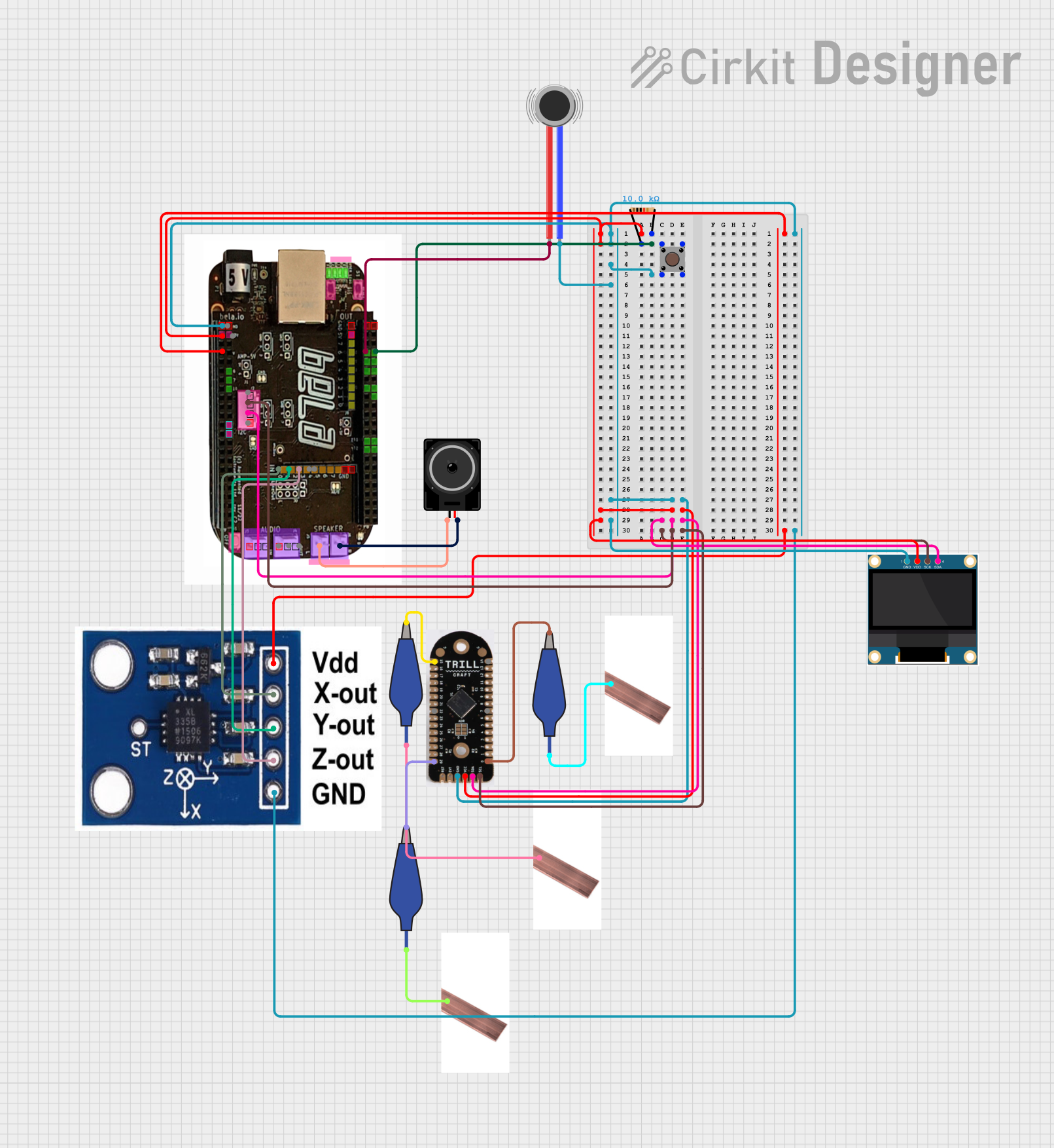 Open Project in Cirkit Designer
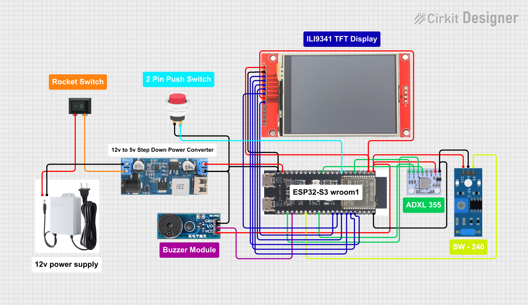 Open Project in Cirkit Designer
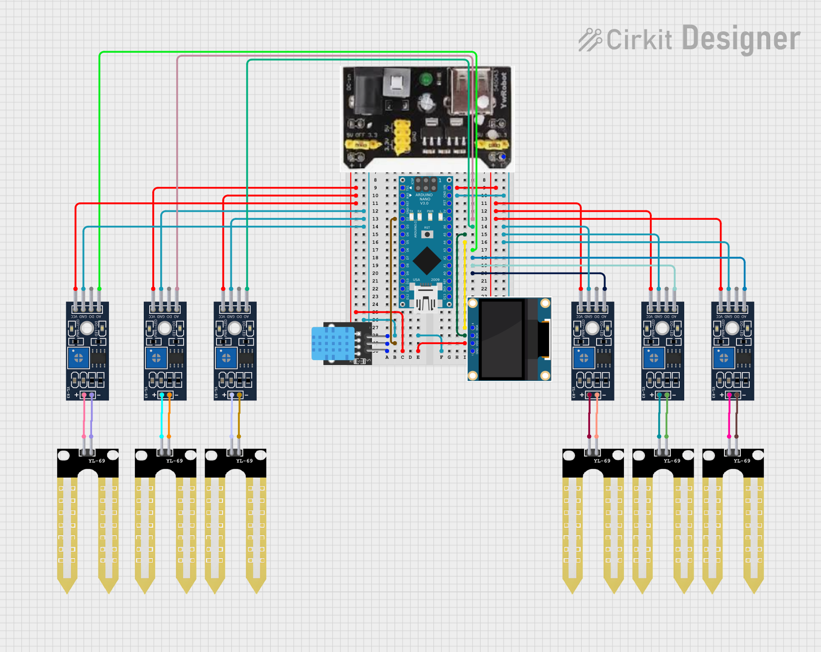 Open Project in Cirkit Designer
Explore Projects Built with YDLIDAR X3
Open Project in Cirkit DesignerOpen Project in Cirkit DesignerOpen Project in Cirkit DesignerOpen Project in Cirkit DesignerCommon Applications
- Robotic navigation and obstacle avoidance
- SLAM-based mapping and localization
- Autonomous vehicles and drones
- Industrial automation and monitoring
- Smart home and IoT applications
Technical Specifications
Key Technical Details
| Parameter | Specification |
|---|---|
| Measurement Range | 0.12 m to 8 m (indoor), 0.12 m to 4 m (outdoor) |
| Scanning Frequency | 6 Hz to 12 Hz (adjustable) |
| Angular Resolution | 0.5° to 1° |
| Field of View (FOV) | 360° |
| Distance Accuracy | ±2% (0.12 m to 1.5 m), ±1% (>1.5 m) |
| Laser Wavelength | 775 nm to 795 nm (Class 1 laser) |
| Communication Interface | UART (3.3V TTL) |
| Power Supply Voltage | 5V DC |
| Operating Current | 500 mA (typical) |
| Dimensions | 70 mm (diameter) x 41 mm (height) |
| Weight | 190 g |
Pin Configuration and Descriptions
The YDLIDAR X3 uses a 4-pin interface for power and communication. Below is the pinout:
| Pin Number | Pin Name | Description |
|---|---|---|
| 1 | VCC | Power supply input (5V DC) |
| 2 | GND | Ground |
| 3 | TX | UART Transmit (data output) |
| 4 | RX | UART Receive (data input) |
Usage Instructions
How to Use the YDLIDAR X3 in a Circuit
- Power Supply: Connect the VCC pin to a stable 5V DC power source and the GND pin to the ground of your circuit.
- Communication: Use the TX and RX pins to establish a UART connection with a microcontroller or computer. Ensure the UART voltage levels are compatible (3.3V TTL).
- Mounting: Secure the YDLIDAR X3 on a stable platform to minimize vibrations during operation.
- Data Processing: Use the provided SDK or libraries to process the data received from the scanner. The SDK supports platforms like Windows, Linux, and ROS (Robot Operating System).
Important Considerations and Best Practices
- Laser Safety: The YDLIDAR X3 uses a Class 1 laser, which is safe under normal operating conditions. Avoid disassembling the device to prevent exposure to laser radiation.
- Power Stability: Ensure a stable 5V power supply to avoid performance issues or damage to the device.
- Environmental Conditions: While the device is suitable for indoor and outdoor use, avoid exposing it to extreme temperatures, high humidity, or direct sunlight for extended periods.
- UART Configuration: Set the UART baud rate to 115200 bps for proper communication.
Example: Connecting YDLIDAR X3 to Arduino UNO
Below is an example of how to connect and use the YDLIDAR X3 with an Arduino UNO:
Wiring Diagram
| YDLIDAR X3 Pin | Arduino UNO Pin |
|---|---|
| VCC | 5V |
| GND | GND |
| TX | RX (Pin 0) |
| RX | TX (Pin 1) |
Arduino Code
#include <SoftwareSerial.h>

// Define RX and TX pins for SoftwareSerial
SoftwareSerial lidarSerial(10, 11); // RX = Pin 10, TX = Pin 11

void setup() {
  Serial.begin(9600); // Initialize Serial Monitor
  lidarSerial.begin(115200); // Initialize YDLIDAR X3 communication

  Serial.println("YDLIDAR X3 Initialized");
}

void loop() {
  // Check if data is available from the LIDAR
  if (lidarSerial.available()) {
    // Read and print data from the LIDAR
    while (lidarSerial.available()) {
      char c = lidarSerial.read();
      Serial.print(c); // Output data to Serial Monitor
    }
    Serial.println(); // Add a newline for readability
  }
}
Notes:
- Use a level shifter if the Arduino operates at 5V logic levels to avoid damaging the YDLIDAR X3.
- The above code assumes the use of SoftwareSerial to free up the hardware UART for debugging.
Troubleshooting and FAQs
Common Issues and Solutions
No Data Output
- Cause: Incorrect UART connection or baud rate mismatch.
- Solution: Verify the TX and RX connections and ensure the baud rate is set to 115200 bps.
Inaccurate Measurements
- Cause: Vibrations or unstable mounting.
- Solution: Secure the device firmly and minimize external vibrations.
Device Not Powering On
- Cause: Insufficient power supply.
- Solution: Ensure the power source provides a stable 5V DC with at least 500 mA current.
Interference in Outdoor Use
- Cause: Strong sunlight or reflective surfaces.
- Solution: Avoid direct sunlight and position the device away from highly reflective objects.
FAQs
Q1: Can the YDLIDAR X3 be used in complete darkness?
A1: Yes, the YDLIDAR X3 operates independently of ambient light and can function in complete darkness.
Q2: Is the YDLIDAR X3 waterproof?
A2: No, the YDLIDAR X3 is not waterproof. Avoid exposing it to water or high humidity.
Q3: Can I adjust the scanning frequency?
A3: Yes, the scanning frequency can be adjusted between 6 Hz and 12 Hz using the SDK or configuration tools.
Q4: Does the YDLIDAR X3 support ROS?
A4: Yes, the YDLIDAR X3 is compatible with ROS, and official drivers are available for integration.
Q5: What is the maximum range of the YDLIDAR X3?
A5: The maximum range is 8 meters indoors and 4 meters outdoors, depending on environmental conditions.