How to Use SILENT STEP CLICK: Examples, Pinouts, and Specs
Introduction
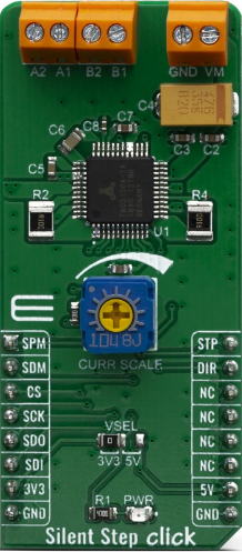
The SILENT STEP CLICK (Manufacturer Part ID: MIKROE-3714) by Mikroelectronica is a compact and efficient tactile switch module designed for applications requiring silent operation. Unlike traditional switches that produce an audible "click" sound, this component provides tactile feedback without noise, making it ideal for environments where noise reduction is critical.
Explore Projects Built with SILENT STEP CLICK
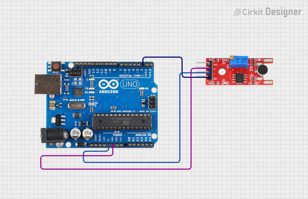
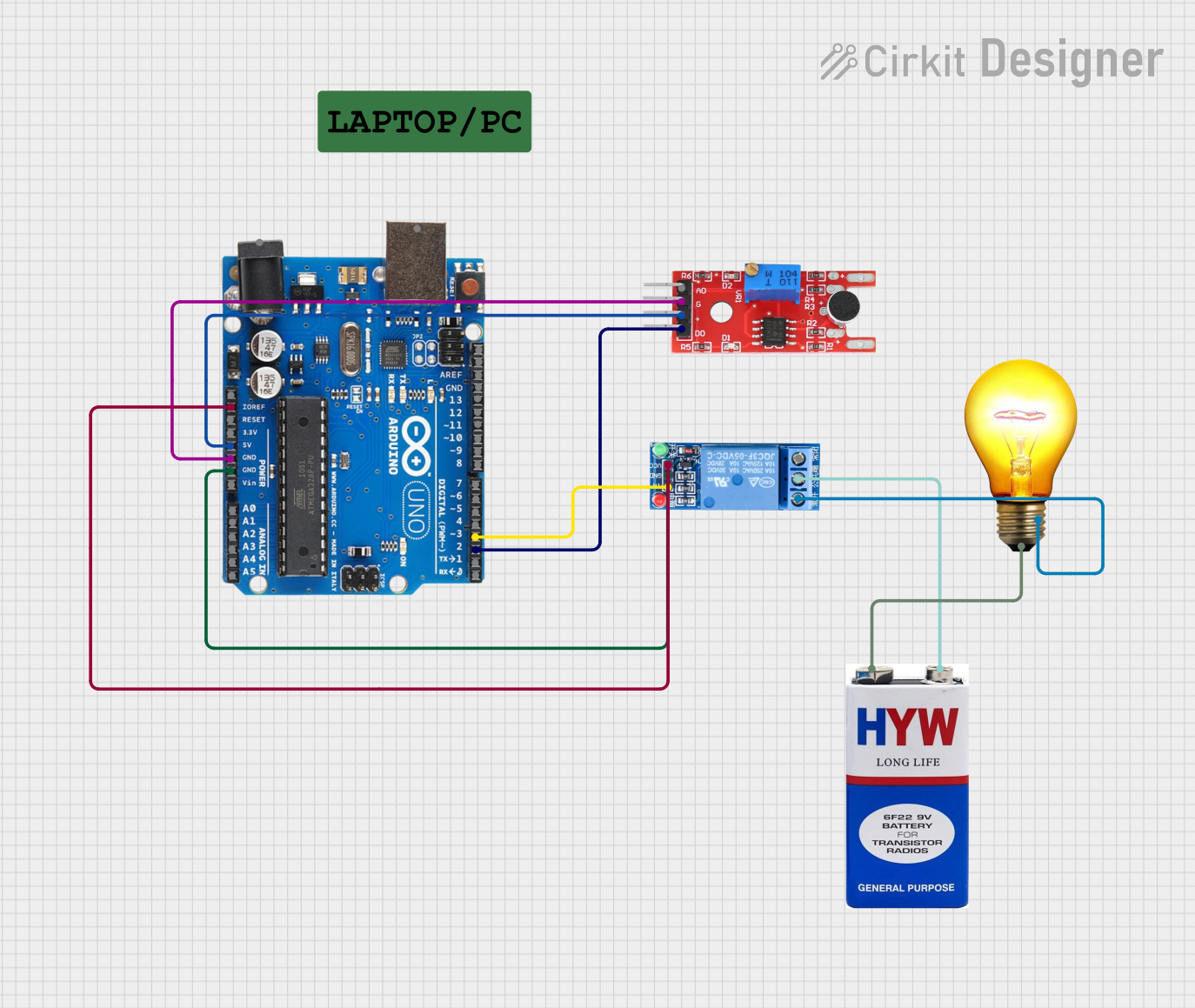
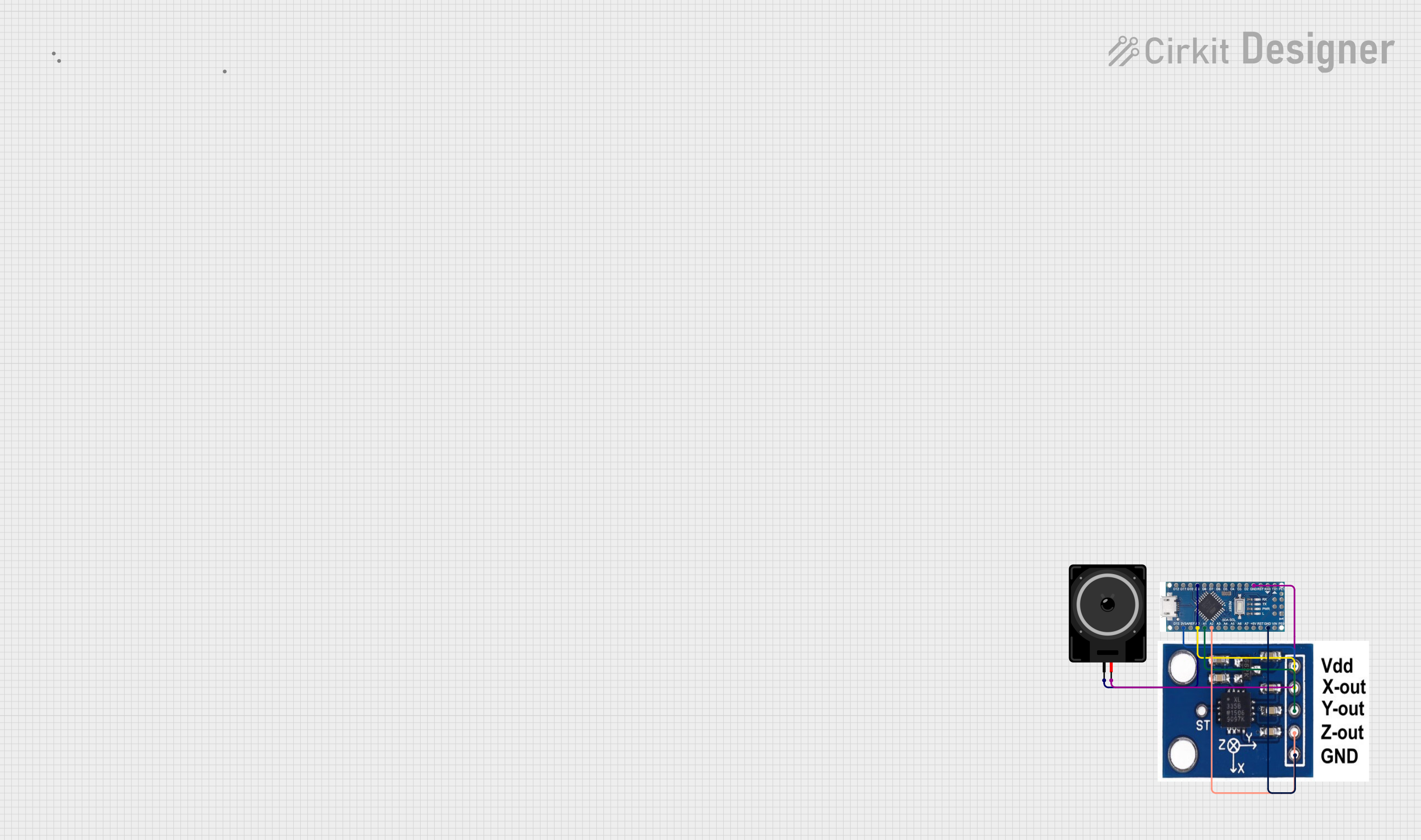
Explore Projects Built with SILENT STEP CLICK
Common Applications
- Keyboards for quiet workspaces
- Control panels in medical or laboratory equipment
- Consumer electronics with noise-sensitive requirements
- Home automation systems
- Gaming peripherals
Technical Specifications
The SILENT STEP CLICK is built for reliability and ease of integration into various electronic systems. Below are its key technical details:
General Specifications
| Parameter | Value |
|---|---|
| Manufacturer | Mikroelectronica |
| Part ID | MIKROE-3714 |
| Operating Voltage | 3.3V or 5V (selectable) |
| Communication Interface | GPIO |
| Dimensions | 28.6mm x 25.4mm |
| Operating Temperature | -40°C to +85°C |
Pin Configuration
The SILENT STEP CLICK uses a standard mikroBUS™ socket for easy integration. Below is the pinout description:
| Pin Name | Pin Type | Description |
|---|---|---|
| AN | Analog | Not used (reserved for future use) |
| RST | Digital | Reset pin (optional, for external reset control) |
| CS | Digital | Chip Select (not used in this module) |
| SCK | Digital | Clock signal (not used in this module) |
| MISO | Digital | Master In Slave Out (not used in this module) |
| MOSI | Digital | Master Out Slave In (not used in this module) |
| PWM | Digital | Output signal from the tactile switch |
| INT | Digital | Interrupt signal triggered by button press |
| TX | UART TX | Not used |
| RX | UART RX | Not used |
| 3.3V | Power | 3.3V power supply |
| 5V | Power | 5V power supply |
| GND | Ground | Ground connection |
Usage Instructions
The SILENT STEP CLICK is straightforward to use and can be integrated into a variety of circuits. Below are the steps and best practices for using this component:
Connecting the SILENT STEP CLICK
- Power Supply: Connect the module to a 3.3V or 5V power source, depending on your system's requirements.
- GPIO Pins: Use the
PWMpin to read the tactile switch's output signal. TheINTpin can be used to detect interrupts triggered by button presses. - Ground Connection: Ensure the
GNDpin is connected to the ground of your circuit.
Example: Using with Arduino UNO
The following example demonstrates how to use the SILENT STEP CLICK with an Arduino UNO to detect button presses:
// Define pin connections
const int buttonPin = 2;  // Connect INT pin of SILENT STEP CLICK to Arduino pin 2
const int ledPin = 13;    // Built-in LED on Arduino for visual feedback

void setup() {
  pinMode(buttonPin, INPUT);  // Set button pin as input
  pinMode(ledPin, OUTPUT);   // Set LED pin as output
  Serial.begin(9600);        // Initialize serial communication
}

void loop() {
  int buttonState = digitalRead(buttonPin);  // Read the button state

  if (buttonState == HIGH) {
    // Button is pressed
    digitalWrite(ledPin, HIGH);  // Turn on LED
    Serial.println("Button Pressed!");  // Print message to serial monitor
  } else {
    // Button is not pressed
    digitalWrite(ledPin, LOW);  // Turn off LED
  }

  delay(50);  // Small delay to debounce the button
}
Best Practices
- Debouncing: Use software or hardware debouncing to avoid false triggers caused by mechanical noise.
- Interrupts: For time-sensitive applications, use the
INTpin to trigger an interrupt service routine (ISR) on button presses. - Voltage Selection: Ensure the correct voltage is selected (3.3V or 5V) to avoid damaging the module.
Troubleshooting and FAQs
Common Issues
No Response from the Button
- Solution: Verify the power supply connections and ensure the module is receiving the correct voltage.
- Tip: Check the
PWMandINTpin connections to the microcontroller.
False Triggers or Noise
- Solution: Implement software debouncing in your code or use a capacitor across the button terminals for hardware debouncing.
- Tip: Ensure the ground connection is stable and free from noise.
Interrupts Not Triggering
- Solution: Confirm that the
INTpin is properly configured as an input in your microcontroller code. - Tip: Test the pin with a simple digital read to ensure it is functioning correctly.
- Solution: Confirm that the
FAQs
Q: Can I use the SILENT STEP CLICK with a 3.3V microcontroller?
A: Yes, the module supports both 3.3V and 5V operation. Ensure the correct voltage is selected.
Q: Is the module compatible with Raspberry Pi?
A: Yes, the SILENT STEP CLICK can be used with Raspberry Pi. Connect the PWM and INT pins to GPIO pins on the Raspberry Pi and configure them accordingly.
Q: How do I debounce the button?
A: You can debounce the button using a small delay in your code (e.g., 50ms) or by adding a capacitor (e.g., 0.1µF) across the button terminals.
By following this documentation, you can effectively integrate and use the SILENT STEP CLICK in your projects.