
How to Use 5V VOLTAGE DETECTOR: Examples, Pinouts, and Specs
 Design with 5V VOLTAGE DETECTOR in Cirkit Designer
Introduction
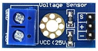
The 5V Voltage Detector is an electronic component designed to monitor and detect when a voltage level reaches or exceeds 5 volts. It is commonly used in circuits to ensure that components operate within their required voltage range, protecting sensitive devices from overvoltage or undervoltage conditions. This component is particularly useful in power supply monitoring, battery management systems, and microcontroller-based projects.
Explore Projects Built with 5V VOLTAGE DETECTOR
 Open Project in Cirkit Designer
 Open Project in Cirkit Designer
 Open Project in Cirkit Designer
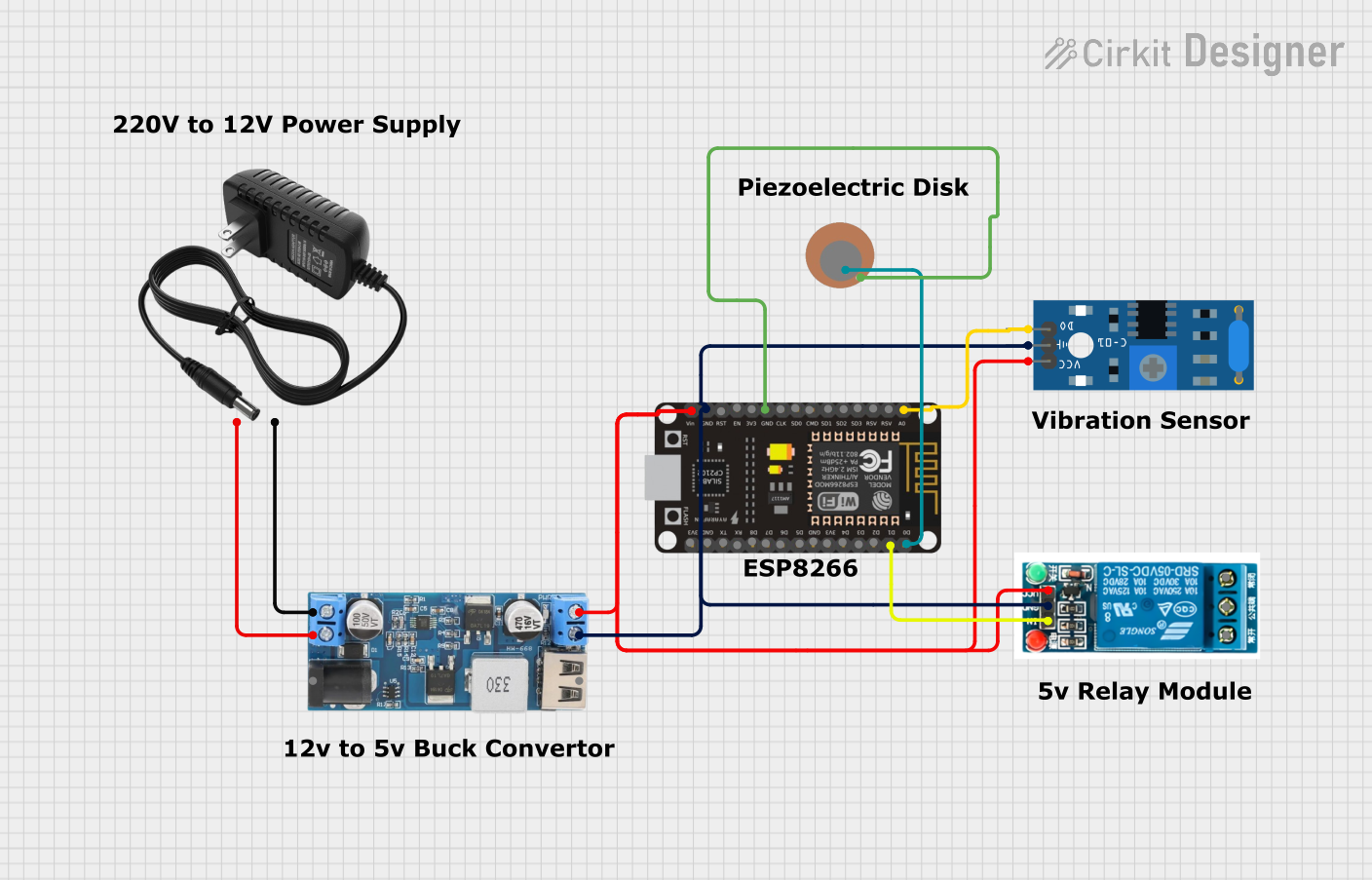 Open Project in Cirkit Designer
Explore Projects Built with 5V VOLTAGE DETECTOR
Open Project in Cirkit DesignerOpen Project in Cirkit DesignerOpen Project in Cirkit DesignerOpen Project in Cirkit DesignerCommon Applications and Use Cases
- Power supply monitoring to ensure stable 5V output.
- Battery level detection in portable devices.
- Voltage threshold detection in microcontroller circuits.
- Overvoltage or undervoltage protection for sensitive components.
- Triggering alarms or indicators when voltage levels deviate.
Technical Specifications
The 5V Voltage Detector is typically a small, integrated circuit or module with the following key specifications:
| Parameter | Value |
|---|---|
| Operating Voltage Range | 2.7V to 6V |
| Detection Voltage | 5.0V ± 0.1V |
| Output Type | Open-Drain or Push-Pull |
| Output Voltage (High) | Vcc (when input voltage ≥ 5V) |
| Output Voltage (Low) | 0V (when input voltage < 5V) |
| Quiescent Current | < 10 µA |
| Response Time | Typically < 20 µs |
| Operating Temperature | -40°C to +85°C |
| Package Type | SOT-23, DIP, or module form |
Pin Configuration and Descriptions
Below is the typical pinout for a 5V Voltage Detector IC in a 3-pin SOT-23 package:
| Pin Number | Pin Name | Description |
|---|---|---|
| 1 | VCC | Power supply input (2.7V to 6V). Connect to the circuit's power source. |
| 2 | GND | Ground connection. Connect to the circuit's ground. |
| 3 | OUT | Output pin. Provides a HIGH or LOW signal based on the input voltage. |
For module-based 5V Voltage Detectors, the pinout may vary slightly, but the functionality remains the same.
Usage Instructions
How to Use the Component in a Circuit
- Power the Detector: Connect the
VCCpin to the power supply (2.7V to 6V) and theGNDpin to the circuit ground. - Monitor Voltage: Connect the voltage to be monitored to the
VCCpin. The detector will compare this voltage to the 5V threshold. - Read the Output: The
OUTpin will output a HIGH signal (logic 1) when the input voltage is equal to or greater than 5V. If the input voltage is below 5V, theOUTpin will output a LOW signal (logic 0). - Connect to a Load or Microcontroller: The
OUTpin can be connected to an LED, buzzer, or microcontroller input pin to trigger an action based on the voltage level.
Important Considerations and Best Practices
- Bypass Capacitor: Place a small bypass capacitor (e.g., 0.1 µF) between
VCCandGNDto filter noise and ensure stable operation. - Pull-Up Resistor: If the
OUTpin is open-drain, connect a pull-up resistor (e.g., 10 kΩ) betweenOUTandVCCto ensure proper logic levels. - Voltage Range: Ensure the monitored voltage does not exceed the maximum operating voltage of the detector (typically 6V).
- Response Time: For applications requiring fast detection, verify that the response time of the detector meets your requirements.
Example: Using with an Arduino UNO
The 5V Voltage Detector can be connected to an Arduino UNO to monitor voltage levels and trigger actions. Below is an example code snippet:
// Define the pin connected to the OUT pin of the 5V Voltage Detector
const int voltageDetectorPin = 2; // Digital pin 2 on Arduino UNO
const int ledPin = 13;            // Built-in LED pin for indication

void setup() {
  pinMode(voltageDetectorPin, INPUT); // Set the detector pin as input
  pinMode(ledPin, OUTPUT);           // Set the LED pin as output
  Serial.begin(9600);                // Initialize serial communication
}

void loop() {
  int detectorState = digitalRead(voltageDetectorPin); // Read the detector output

  if (detectorState == HIGH) {
    // Voltage is 5V or higher
    digitalWrite(ledPin, HIGH); // Turn on the LED
    Serial.println("Voltage is 5V or higher!");
  } else {
    // Voltage is below 5V
    digitalWrite(ledPin, LOW);  // Turn off the LED
    Serial.println("Voltage is below 5V.");
  }

  delay(500); // Wait for 500ms before the next reading
}
Troubleshooting and FAQs
Common Issues and Solutions
No Output Signal:
- Cause: Incorrect wiring or loose connections.
- Solution: Double-check all connections, especially
VCC,GND, andOUT.
Output Always LOW:
- Cause: Input voltage is below the 5V threshold.
- Solution: Verify the input voltage using a multimeter. Ensure it is within the operating range.
Output Always HIGH:
- Cause: Input voltage is consistently above 5V.
- Solution: Check the input voltage and ensure it is not exceeding the maximum operating voltage.
Fluctuating Output:
- Cause: Noise or unstable power supply.
- Solution: Add a bypass capacitor (e.g., 0.1 µF) between
VCCandGND.
FAQs
Q: Can the 5V Voltage Detector be used with voltages higher than 6V?
A: No, the detector is designed for a maximum operating voltage of 6V. Using higher voltages may damage the component.
Q: What happens if the input voltage is exactly 5V?
A: The OUT pin will output a HIGH signal, indicating that the voltage is at or above the threshold.
Q: Can I use this detector with a 3.3V system?
A: Yes, as long as the operating voltage of the detector is compatible with the 3.3V system. However, the detection threshold will remain at 5V.
Q: Is the output pin capable of driving a load directly?
A: The output pin can drive small loads, but for larger loads, use a transistor or relay as an intermediary.
This concludes the documentation for the 5V Voltage Detector.