
How to Use Voltage Regulator: Examples, Pinouts, and Specs
 Design with Voltage Regulator in Cirkit Designer
Introduction
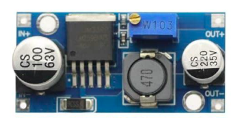
The Valefod LM2596 Voltage Regulator is a high-efficiency device designed to maintain a constant output voltage, regardless of variations in input voltage or load conditions. This ensures a stable power supply for sensitive electronic circuits, protecting them from voltage fluctuations that could cause damage or erratic behavior.
Common applications of the LM2596 include:
- Powering microcontrollers and sensors in embedded systems
- Voltage regulation in battery-powered devices
- Step-down (buck) voltage conversion for DC-DC applications
- Power supply stabilization for audio and communication equipment
Explore Projects Built with Voltage Regulator
 Open Project in Cirkit Designer
 Open Project in Cirkit Designer
 Open Project in Cirkit Designer
 Open Project in Cirkit Designer
Explore Projects Built with Voltage Regulator
Open Project in Cirkit DesignerOpen Project in Cirkit DesignerOpen Project in Cirkit DesignerOpen Project in Cirkit DesignerTechnical Specifications
The LM2596 is a step-down (buck) voltage regulator with the following key specifications:
| Parameter | Value |
|---|---|
| Input Voltage Range | 4.5V to 40V |
| Output Voltage Range | 1.23V to 37V (adjustable) |
| Output Current | Up to 3A |
| Efficiency | Up to 92% |
| Switching Frequency | 150 kHz |
| Operating Temperature | -40°C to +125°C |
| Package Type | TO-220 or TO-263 |
Pin Configuration and Descriptions
The LM2596 has 5 pins, as described in the table below:
| Pin Number | Pin Name | Description |
|---|---|---|
| 1 | Input (Vin) | Connects to the unregulated input voltage source. |
| 2 | Output (Vout) | Provides the regulated output voltage. |
| 3 | Ground (GND) | Common ground for input and output. |
| 4 | Feedback (FB) | Used to set the output voltage via a resistor divider. |
| 5 | ON/OFF | Enables or disables the regulator (optional). |
Usage Instructions
How to Use the LM2596 in a Circuit
Connect the Input Voltage (Vin):
Attach the unregulated DC voltage source (4.5V to 40V) to theVinpin. Ensure the input voltage is higher than the desired output voltage by at least 1.5V for proper operation.Set the Output Voltage (Vout):
Use a resistor divider network connected to theFeedback (FB)pin to set the desired output voltage. The output voltage can be calculated using the formula:
[ V_{out} = V_{ref} \times \left(1 + \frac{R_2}{R_1}\right) ]
where ( V_{ref} ) is 1.23V (internal reference voltage).Connect the Load:
Attach the load to theVoutpin. Ensure the load does not exceed the maximum output current of 3A.Optional ON/OFF Control:
If you wish to enable or disable the regulator, connect a control signal to theON/OFFpin. Pulling this pin low disables the regulator, while leaving it high enables normal operation.Add External Components:
- Place an input capacitor (e.g., 100 µF) between
VinandGNDto filter input noise. - Place an output capacitor (e.g., 220 µF) between
VoutandGNDto stabilize the output voltage. - Use an inductor (e.g., 33 µH) as part of the buck converter circuit for efficient operation.
- Place an input capacitor (e.g., 100 µF) between
Example: Using LM2596 with Arduino UNO
The LM2596 can be used to power an Arduino UNO by stepping down a 12V input to 5V. Below is an example circuit and Arduino code:
Circuit Connections:
- Connect a 12V DC power source to the
Vinpin of the LM2596. - Set the output voltage to 5V using the resistor divider.
- Connect the
Voutpin to the Arduino UNO's 5V pin. - Connect the
GNDpin to the Arduino's GND.
Arduino Code:
// Example code to blink an LED using Arduino UNO powered by LM2596
const int ledPin = 13; // Pin 13 is connected to the onboard LED

void setup() {
  pinMode(ledPin, OUTPUT); // Set pin 13 as an output
}

void loop() {
  digitalWrite(ledPin, HIGH); // Turn the LED on
  delay(1000);               // Wait for 1 second
  digitalWrite(ledPin, LOW);  // Turn the LED off
  delay(1000);               // Wait for 1 second
}
Important Considerations and Best Practices
- Heat Dissipation: The LM2596 can generate heat during operation, especially at high currents. Use a heatsink or ensure proper ventilation to prevent overheating.
- Input Voltage Margin: Always ensure the input voltage is at least 1.5V higher than the desired output voltage.
- Capacitor Selection: Use low-ESR capacitors for better performance and stability.
- Inductor Selection: Choose an inductor with a current rating higher than the maximum load current.
Troubleshooting and FAQs
Common Issues and Solutions
Output Voltage is Incorrect:
- Verify the resistor divider values used to set the output voltage.
- Check for loose or incorrect connections in the circuit.
Regulator Overheats:
- Ensure the load current does not exceed 3A.
- Use a heatsink or improve airflow around the regulator.
No Output Voltage:
- Check if the
ON/OFFpin is properly configured (should be high for normal operation). - Verify that the input voltage is within the specified range.
- Check if the
Output Voltage is Unstable:
- Ensure proper capacitor values are used at the input and output.
- Check for noise or interference in the input power supply.
FAQs
Q: Can the LM2596 be used for step-up (boost) voltage conversion?
A: No, the LM2596 is a step-down (buck) regulator and cannot increase the input voltage.
Q: What is the maximum efficiency of the LM2596?
A: The LM2596 can achieve an efficiency of up to 92%, depending on the input voltage, output voltage, and load conditions.
Q: Can I use the LM2596 with an AC power source?
A: No, the LM2596 requires a DC input voltage. Use a rectifier and filter circuit to convert AC to DC before connecting to the regulator.
Q: How do I calculate the resistor values for the feedback pin?
A: Use the formula ( V_{out} = V_{ref} \times \left(1 + \frac{R_2}{R_1}\right) ), where ( V_{ref} = 1.23V ). Select ( R_1 ) and ( R_2 ) to achieve the desired output voltage.
This concludes the documentation for the Valefod LM2596 Voltage Regulator.