How to Use UPS HAT(E): Examples, Pinouts, and Specs
Introduction
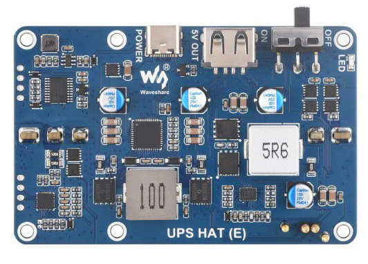
The UPS HAT (E) is an advanced add-on board designed to provide uninterruptible power supply functionality for single-board computers, such as the Raspberry Pi. This HAT ensures continuous operation during power outages by seamlessly switching to battery power when the primary power source is interrupted. It also includes power management features, such as battery monitoring and safe shutdown capabilities, to protect your device and data.
Explore Projects Built with UPS HAT(E)


Explore Projects Built with UPS HAT(E)
Common Applications and Use Cases
- IoT Devices: Ensures uninterrupted operation of Internet of Things (IoT) systems during power failures.
- Home Automation: Keeps smart home systems running without interruption.
- Edge Computing: Provides reliable power for edge devices in remote or unstable power environments.
- Data Logging: Prevents data loss in applications requiring continuous data collection.
- Portable Projects: Powers Raspberry Pi-based portable devices with rechargeable battery support.
Technical Specifications
Key Technical Details
- Input Voltage: 5V DC (via micro-USB or GPIO header)
- Output Voltage: 5V DC (regulated)
- Maximum Output Current: 2.5A
- Battery Type: Lithium-ion or Lithium-polymer (3.7V, single-cell)
- Battery Capacity: Supports batteries up to 5000mAh
- Charging Current: 1A (max)
- Communication Interface: I2C for battery status monitoring
- Dimensions: 65mm x 56mm (compatible with Raspberry Pi form factor)
Pin Configuration and Descriptions
The UPS HAT (E) connects to the Raspberry Pi via the GPIO header. Below is the pin configuration:
| Pin | Name | Description |
|---|---|---|
| 1 | 3.3V | Power supply for the HAT's logic circuitry. |
| 2 | 5V | Main power input/output for the Raspberry Pi and peripherals. |
| 3 | SDA (I2C) | Data line for I2C communication (used for battery status monitoring). |
| 5 | SCL (I2C) | Clock line for I2C communication. |
| 6 | GND | Ground connection. |
| 7 | Power Key | Optional pin to trigger a safe shutdown or wake-up signal. |
| 8 | Battery+ | Positive terminal for the external battery connection. |
| 9 | Battery- | Negative terminal for the external battery connection. |
Usage Instructions
How to Use the UPS HAT (E) in a Circuit
- Attach the HAT: Securely mount the UPS HAT (E) onto the GPIO header of your Raspberry Pi.
- Connect a Battery: Attach a 3.7V lithium-ion or lithium-polymer battery to the
Battery+andBattery-terminals. - Power the HAT: Supply 5V DC power to the HAT via the micro-USB port or GPIO header.
- Monitor Battery Status: Use the I2C interface to read battery voltage, charge percentage, and other parameters.
- Enable Safe Shutdown: Configure the Raspberry Pi to safely shut down when the battery level is critically low.
Important Considerations and Best Practices
- Battery Selection: Use only high-quality, compatible lithium-ion or lithium-polymer batteries to ensure safety and performance.
- Ventilation: Ensure proper ventilation to prevent overheating during charging or high current draw.
- Firmware Updates: Check for firmware updates from the manufacturer to improve functionality and compatibility.
- I2C Address Conflicts: If using other I2C devices, ensure there are no address conflicts with the UPS HAT (E).
Example Code for Raspberry Pi
Below is an example Python script to monitor the battery status using the I2C interface:
import smbus
import time
Initialize I2C bus
bus = smbus.SMBus(1) # Use I2C bus 1 on Raspberry Pi
UPS HAT I2C address (replace with the correct address if different)
UPS_HAT_I2C_ADDRESS = 0x36
def read_battery_voltage(): # Read two bytes of data from the voltage register (0x02) data = bus.read_word_data(UPS_HAT_I2C_ADDRESS, 0x02) # Convert the data to voltage (in millivolts) voltage = ((data & 0xFF) << 8 | (data >> 8)) * 1.25 / 1000 return voltage
def read_battery_percentage(): # Read two bytes of data from the percentage register (0x04) data = bus.read_word_data(UPS_HAT_I2C_ADDRESS, 0x04) # Convert the data to percentage percentage = (data & 0xFF) << 8 | (data >> 8) return percentage / 256
try: while True: voltage = read_battery_voltage() percentage = read_battery_percentage() print(f"Battery Voltage: {voltage:.2f}V") print(f"Battery Percentage: {percentage:.2f}%") time.sleep(5) # Wait for 5 seconds before the next reading except KeyboardInterrupt: print("Exiting program.")
Notes:
- Install the
smbuslibrary usingsudo apt-get install python3-smbusif not already installed. - Replace the I2C address (
0x36) with the correct address if your UPS HAT uses a different one.
Troubleshooting and FAQs
Common Issues and Solutions
HAT Not Powering the Raspberry Pi
- Cause: Insufficient battery charge or incorrect battery connection.
- Solution: Ensure the battery is fully charged and properly connected to the
Battery+andBattery-terminals.
I2C Communication Fails
- Cause: Incorrect I2C address or bus configuration.
- Solution: Verify the I2C address of the UPS HAT and ensure the Raspberry Pi's I2C interface is enabled in the
raspi-configtool.
Overheating During Operation
- Cause: High current draw or poor ventilation.
- Solution: Reduce the load on the Raspberry Pi or improve airflow around the HAT.
Battery Not Charging
- Cause: Faulty battery or insufficient input power.
- Solution: Test with a different battery and ensure the input power supply provides at least 5V and 2A.
FAQs
Can I use the UPS HAT (E) with other single-board computers?
- Yes, as long as the GPIO pinout and power requirements are compatible.
What happens when the battery is fully discharged?
- The UPS HAT will shut down the Raspberry Pi safely to prevent data loss and battery damage.
Can I monitor the battery status without using I2C?
- No, the I2C interface is required to access battery status information.
Is the UPS HAT (E) hot-swappable?
- Yes, you can connect or disconnect the external power supply without interrupting operation, as long as the battery is connected.