How to Use 0.96 OLED: Examples, Pinouts, and Specs
Introduction
The 0.96 OLED display module is a compact, low-power display that utilizes organic light-emitting diodes to produce bright and colorful images. Manufactured by Arduino with the part ID "UNO," this module features a resolution of 128x64 pixels, making it ideal for displaying text, graphics, and simple animations. Its small size and energy efficiency make it a popular choice for embedded systems, IoT devices, and microcontroller-based projects.
Explore Projects Built with 0.96 OLED


Explore Projects Built with 0.96 OLED
Common Applications
- Displaying sensor data in IoT projects
- Creating user interfaces for embedded systems
- Visualizing real-time data in robotics
- Portable devices and wearables
- Debugging and testing microcontroller outputs
Technical Specifications
The following table outlines the key technical details of the 0.96 OLED display module:
| Parameter | Specification |
|---|---|
| Display Type | OLED (Organic Light-Emitting Diode) |
| Resolution | 128x64 pixels |
| Interface | I2C (Inter-Integrated Circuit) |
| Operating Voltage | 3.3V - 5V |
| Current Consumption | ~20mA |
| Dimensions | 27mm x 27mm x 4mm |
| Viewing Angle | >160° |
| Operating Temperature | -40°C to +85°C |
Pin Configuration
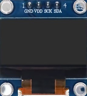
The 0.96 OLED module typically has a 4-pin interface for I2C communication. The pin configuration is as follows:
| Pin | Name | Description |
|---|---|---|
| 1 | GND | Ground pin, connect to the ground of the circuit. |
| 2 | VCC | Power supply pin, connect to 3.3V or 5V. |
| 3 | SCL | Serial Clock Line for I2C communication. |
| 4 | SDA | Serial Data Line for I2C communication. |
Usage Instructions
Connecting the 0.96 OLED to an Arduino UNO
To use the 0.96 OLED module with an Arduino UNO, follow these steps:
- Wiring: Connect the OLED module to the Arduino UNO as shown below:
- GND → GND
- VCC → 5V
- SCL → A5 (I2C Clock)
- SDA → A4 (I2C Data)
- Install Libraries: Install the
Adafruit_GFXandAdafruit_SSD1306libraries in the Arduino IDE. These libraries provide functions for controlling the OLED display. - Upload Code: Use the example code below to display text on the OLED.
Example Code
#include <Wire.h>
#include <Adafruit_GFX.h>
#include <Adafruit_SSD1306.h>

// Define the OLED display width and height
#define SCREEN_WIDTH 128
#define SCREEN_HEIGHT 64

// Create an SSD1306 display object connected via I2C
Adafruit_SSD1306 display(SCREEN_WIDTH, SCREEN_HEIGHT, &Wire, -1);

void setup() {
  // Initialize the display
  if (!display.begin(SSD1306_I2C_ADDRESS, 0x3C)) {
    // If the display fails to initialize, print an error message
    Serial.println(F("SSD1306 allocation failed"));
    for (;;); // Stop execution
  }

  // Clear the display buffer
  display.clearDisplay();

  // Set text size and color
  display.setTextSize(1); // Text size multiplier
  display.setTextColor(SSD1306_WHITE);

  // Display a message
  display.setCursor(0, 0); // Set cursor to top-left corner
  display.println(F("Hello, OLED!"));
  display.display(); // Render the text on the screen
}

void loop() {
  // No actions in the loop for this example
}
Best Practices
- Ensure the OLED module is powered within its operating voltage range (3.3V - 5V).
- Use pull-up resistors on the I2C lines (SCL and SDA) if not already included on the module.
- Avoid exposing the OLED to direct sunlight for extended periods to prevent damage.
Troubleshooting and FAQs
Common Issues
The display does not turn on:
- Verify the wiring connections, especially GND and VCC.
- Ensure the I2C address (default: 0x3C) matches the one in your code.
- Check if the OLED module is receiving power (use a multimeter if necessary).
Text or graphics are not displayed correctly:
- Confirm that the correct resolution (128x64) is set in the code.
- Ensure the
Adafruit_GFXandAdafruit_SSD1306libraries are installed and up-to-date.
Flickering or unstable display:
- Check for loose connections on the I2C lines.
- Use shorter wires to reduce noise in the I2C communication.
FAQs
Q: Can I use the 0.96 OLED with a 3.3V microcontroller?
A: Yes, the OLED module supports both 3.3V and 5V logic levels.
Q: How do I display custom graphics on the OLED?
A: Use the Adafruit_GFX library to draw shapes or load bitmap images. Refer to the library documentation for detailed instructions.
Q: What is the maximum I2C communication speed supported?
A: The OLED module typically supports I2C speeds up to 400kHz (Fast Mode).
By following this documentation, you can effectively integrate the 0.96 OLED display into your projects and troubleshoot common issues with ease.