How to Use pwm to voltage : Examples, Pinouts, and Specs
Introduction
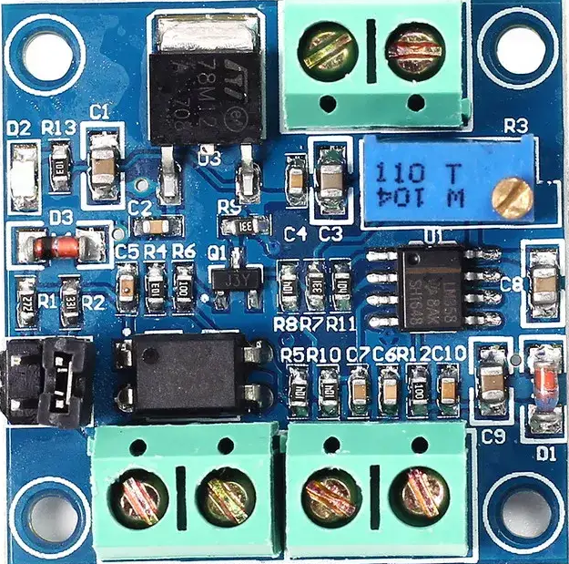
A PWM to Voltage Converter is an electronic component that transforms pulse-width modulation (PWM) signals into a corresponding analog voltage level. This conversion is essential in applications where analog control is required but the controlling device (e.g., a microcontroller) outputs only PWM signals. By interpreting the duty cycle of the PWM signal, the converter generates a proportional DC voltage.
Explore Projects Built with pwm to voltage


Explore Projects Built with pwm to voltage
Common Applications and Use Cases
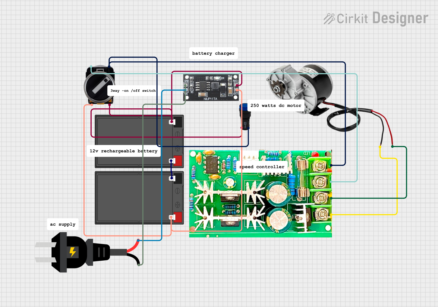
- Motor speed control in industrial and hobbyist projects
- LED brightness adjustment
- Analog signal generation for audio or control systems
- Interfacing PWM-based microcontrollers (e.g., Arduino, Raspberry Pi) with analog devices
- Voltage-controlled devices such as amplifiers or actuators
Technical Specifications
Below are the typical specifications for a PWM to Voltage Converter. Note that actual values may vary depending on the specific model or manufacturer.
| Parameter | Specification |
|---|---|
| Input Voltage Range | 3.3V to 24V |
| Output Voltage Range | 0V to 10V (proportional to PWM duty cycle) |
| PWM Input Frequency | 1 kHz to 10 kHz |
| Input PWM Duty Cycle | 0% to 100% |
| Output Current Capability | Up to 10 mA |
| Conversion Accuracy | ±1% |
| Operating Temperature | -40°C to 85°C |
Pin Configuration and Descriptions
| Pin Name | Description |
|---|---|
| VCC | Power supply input (3.3V to 24V) |
| GND | Ground connection |
| PWM_IN | PWM signal input (from microcontroller or other source) |
| V_OUT | Analog voltage output (proportional to PWM duty cycle) |
Usage Instructions
How to Use the Component in a Circuit
- Power the Converter: Connect the VCC pin to a suitable power source (e.g., 5V or 12V) and the GND pin to the ground of your circuit.
- Input PWM Signal: Connect the PWM_IN pin to the PWM output of your microcontroller or other signal source. Ensure the PWM signal frequency is within the supported range (e.g., 1 kHz to 10 kHz).
- Output Voltage: The V_OUT pin will provide an analog voltage proportional to the duty cycle of the PWM signal. For example:
- A 50% duty cycle PWM signal will produce approximately half of the maximum output voltage.
- A 100% duty cycle will produce the maximum output voltage.
Important Considerations and Best Practices
- Filter Capacitor: Many PWM to Voltage Converters include an onboard low-pass filter to smooth the PWM signal into a stable DC voltage. If your converter does not include this, you may need to add an external RC filter.
- PWM Frequency: Ensure the PWM signal frequency is within the specified range. Frequencies too low may result in unstable or inaccurate output voltages.
- Load Impedance: Avoid connecting loads with very low impedance directly to the V_OUT pin, as this may exceed the current capability of the converter.
- Calibration: Some converters include a potentiometer for fine-tuning the output voltage. Adjust this as needed for precise control.
Example: Using with an Arduino UNO
Below is an example of how to use a PWM to Voltage Converter with an Arduino UNO to control the output voltage.
Circuit Connections
- Connect the VCC pin of the converter to the 5V pin of the Arduino.
- Connect the GND pin of the converter to the GND pin of the Arduino.
- Connect the PWM_IN pin of the converter to pin 9 of the Arduino (a PWM-capable pin).
- Measure the output voltage at the V_OUT pin using a multimeter or connect it to an analog device.
Arduino Code
// Example code to generate a PWM signal on pin 9 of Arduino UNO
// This will vary the duty cycle from 0% to 100% in steps of 10%.

void setup() {
  pinMode(9, OUTPUT); // Set pin 9 as an output for PWM signal
}

void loop() {
  for (int dutyCycle = 0; dutyCycle <= 255; dutyCycle += 25) {
    analogWrite(9, dutyCycle); // Write PWM signal with varying duty cycle
    delay(500); // Wait for 500ms to observe the change in output voltage
  }
}
Notes on the Code
- The
analogWrite()function generates a PWM signal on pin 9. The duty cycle is controlled by the value passed to the function (0 for 0% duty cycle, 255 for 100% duty cycle). - The output voltage at the V_OUT pin will change proportionally to the duty cycle.
Troubleshooting and FAQs
Common Issues and Solutions
No Output Voltage
- Cause: Incorrect wiring or no PWM signal input.
- Solution: Verify all connections and ensure the PWM_IN pin is receiving a valid PWM signal.
Unstable Output Voltage
- Cause: PWM frequency is too low or insufficient filtering.
- Solution: Increase the PWM frequency or add an external low-pass filter.
Output Voltage Does Not Match Expected Value
- Cause: Calibration issue or incorrect duty cycle.
- Solution: Adjust the onboard potentiometer (if available) or verify the PWM duty cycle.
Overheating
- Cause: Excessive current draw from the V_OUT pin.
- Solution: Ensure the load connected to the V_OUT pin does not exceed the current rating of the converter.
FAQs
Q: Can I use this converter with a 3.3V microcontroller?
A: Yes, as long as the PWM signal voltage level is compatible with the converter's input specifications.
Q: What happens if the PWM frequency is too high?
A: If the frequency exceeds the supported range, the converter may not accurately generate the corresponding analog voltage.
Q: Can I use this converter to control a motor directly?
A: No, the output current capability is typically too low to drive a motor directly. Use the output voltage to control a motor driver or amplifier instead.