
How to Use Buzzer Passive: Examples, Pinouts, and Specs
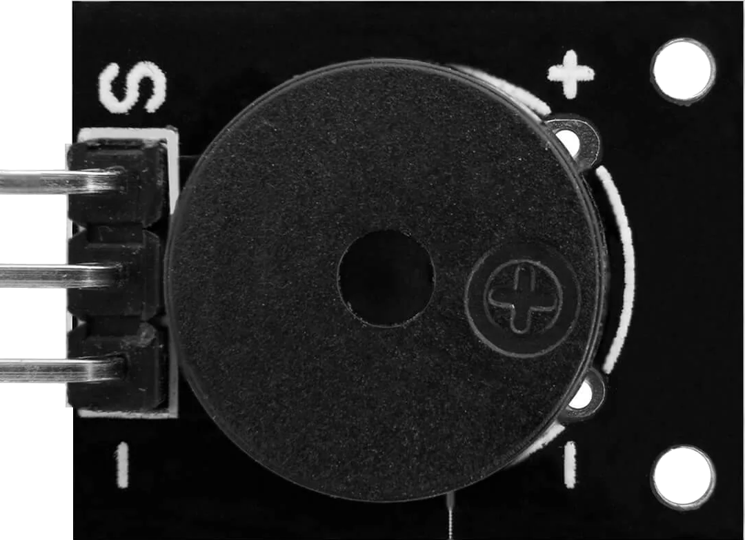
 Design with Buzzer Passive in Cirkit Designer
Introduction
The AZDelivery KY-006 Passive Buzzer is an audio signaling device that produces sound when an alternating current (AC) signal is applied. Unlike an active buzzer, which generates sound internally, the passive buzzer requires an external signal, such as a square wave, to produce sound. This makes it versatile for applications where precise control over sound frequency and duration is required.
Explore Projects Built with Buzzer Passive
 Open Project in Cirkit Designer
 Open Project in Cirkit Designer
 Open Project in Cirkit Designer
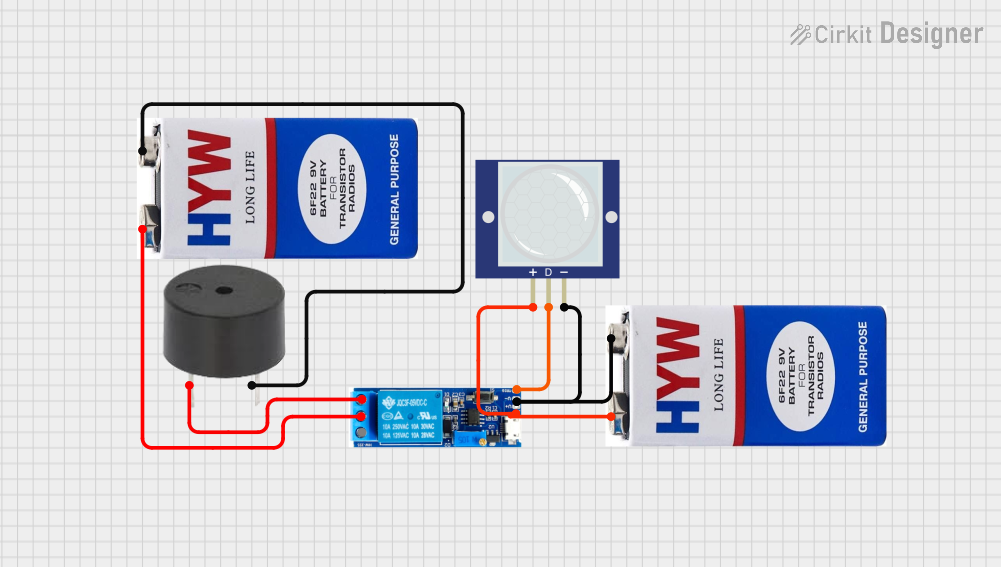 Open Project in Cirkit Designer
Explore Projects Built with Buzzer Passive
Open Project in Cirkit DesignerOpen Project in Cirkit DesignerOpen Project in Cirkit DesignerOpen Project in Cirkit DesignerCommon Applications and Use Cases
- Alarms and notifications in electronic devices
- Sound effects in embedded systems
- Timers and reminders
- Educational projects and prototyping
- Arduino-based projects for generating tones or melodies
Technical Specifications
Below are the key technical details for the KY-006 Passive Buzzer:
| Parameter | Value |
|---|---|
| Manufacturer | AZDelivery |
| Part ID | KY-006 |
| Operating Voltage | 3.3V to 5V |
| Operating Current | ≤ 25mA |
| Resonant Frequency | ~2 kHz |
| Sound Pressure Level | ≥ 85 dB (at 10 cm, 5V input) |
| Dimensions | 18.5mm x 15mm x 11.5mm |
| Weight | ~2g |
Pin Configuration and Descriptions
The KY-006 Passive Buzzer module has three pins, as described below:
| Pin | Label | Description |
|---|---|---|
| 1 | Signal (S) | Input pin for the control signal (e.g., PWM) |
| 2 | VCC | Power supply pin (3.3V to 5V) |
| 3 | GND | Ground pin |
Note: The module typically comes with a 3-pin header, but only the
SignalandGNDpins are required for operation. TheVCCpin is internally connected to theSignalpin.
Usage Instructions
How to Use the KY-006 Passive Buzzer in a Circuit
Connect the Pins:
- Connect the
Signalpin to a PWM-capable pin on your microcontroller (e.g., Arduino). - Connect the
GNDpin to the ground of your circuit. - Optionally, connect the
VCCpin to the power supply if required.
- Connect the
Generate a Signal:
- Use a PWM signal to drive the buzzer. The frequency of the PWM signal determines the tone produced by the buzzer.
Test the Buzzer:
- Upload a test program to your microcontroller to generate a square wave signal and verify the buzzer's operation.
Important Considerations and Best Practices
- Signal Frequency: The buzzer resonates best at ~2 kHz, but it can produce sound across a range of frequencies. Experiment with different frequencies to achieve the desired tone.
- Power Supply: Ensure the power supply voltage is within the specified range (3.3V to 5V) to avoid damaging the component.
- Avoid Continuous Operation: Prolonged operation at high volumes may reduce the buzzer's lifespan. Use it intermittently for alarms or notifications.
Example Code for Arduino UNO
Below is an example Arduino sketch to generate a tone using the KY-006 Passive Buzzer:
// Example code for KY-006 Passive Buzzer with Arduino UNO
// Generates a tone at 2 kHz for 1 second, then pauses for 1 second

#define BUZZER_PIN 8  // Connect the Signal pin of the buzzer to digital pin 8

void setup() {
  pinMode(BUZZER_PIN, OUTPUT);  // Set the buzzer pin as an output
}

void loop() {
  tone(BUZZER_PIN, 2000);  // Generate a 2 kHz tone on the buzzer pin
  delay(1000);             // Wait for 1 second
  noTone(BUZZER_PIN);      // Stop the tone
  delay(1000);             // Wait for 1 second
}
Note: The
tone()function is used to generate a square wave signal. ThenoTone()function stops the signal.
Troubleshooting and FAQs
Common Issues and Solutions
No Sound from the Buzzer:
- Cause: Incorrect wiring or insufficient signal.
- Solution: Verify the connections. Ensure the
Signalpin is connected to a PWM-capable pin and that the microcontroller is generating a signal.
Low Volume or Distorted Sound:
- Cause: Incorrect signal frequency or insufficient power supply.
- Solution: Use a frequency close to the buzzer's resonant frequency (~2 kHz). Ensure the power supply voltage is within the specified range.
Buzzer Produces a Continuous Tone:
- Cause: The
Signalpin is held HIGH instead of receiving a PWM signal. - Solution: Use a PWM signal or the
tone()function to generate the desired sound.
- Cause: The
Buzzer Gets Hot:
- Cause: Overvoltage or prolonged operation.
- Solution: Check the power supply voltage and avoid continuous operation at high volumes.
FAQs
Q1: Can I use the KY-006 Passive Buzzer without a microcontroller?
A1: Yes, you can use an external oscillator circuit to generate a square wave signal, but a microcontroller like Arduino is more convenient for precise control.
Q2: What is the difference between a passive and an active buzzer?
A2: A passive buzzer requires an external signal to produce sound, while an active buzzer has an internal oscillator and only needs a DC voltage to operate.
Q3: Can I use the KY-006 Passive Buzzer with a 3.3V microcontroller?
A3: Yes, the buzzer operates within a voltage range of 3.3V to 5V, making it compatible with 3.3V systems like ESP32 or Raspberry Pi.
Q4: How do I change the tone produced by the buzzer?
A4: Adjust the frequency of the PWM signal. Higher frequencies produce higher-pitched tones, while lower frequencies produce lower-pitched tones.