How to Use 3P Breaker: Examples, Pinouts, and Specs
Introduction
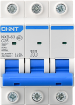
A 3P (three-pole) breaker is a protective device designed to safeguard electrical circuits by interrupting the flow of current in the event of an overload or short circuit. It is specifically engineered for three-phase systems, which are commonly used in industrial, commercial, and large-scale residential applications. The 3P breaker ensures the safety of equipment and personnel by isolating all three phases simultaneously during a fault condition.
Explore Projects Built with 3P Breaker

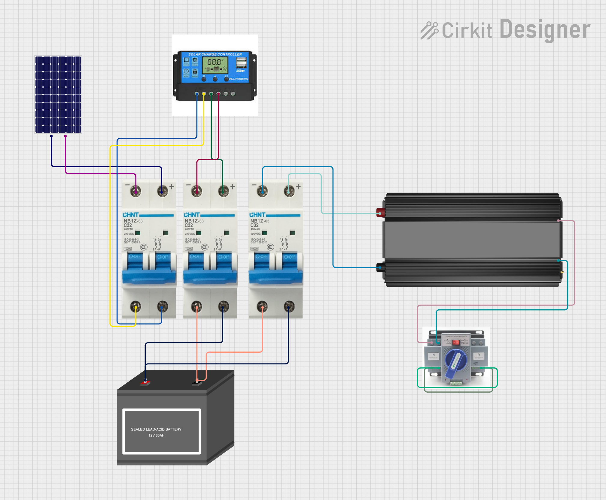
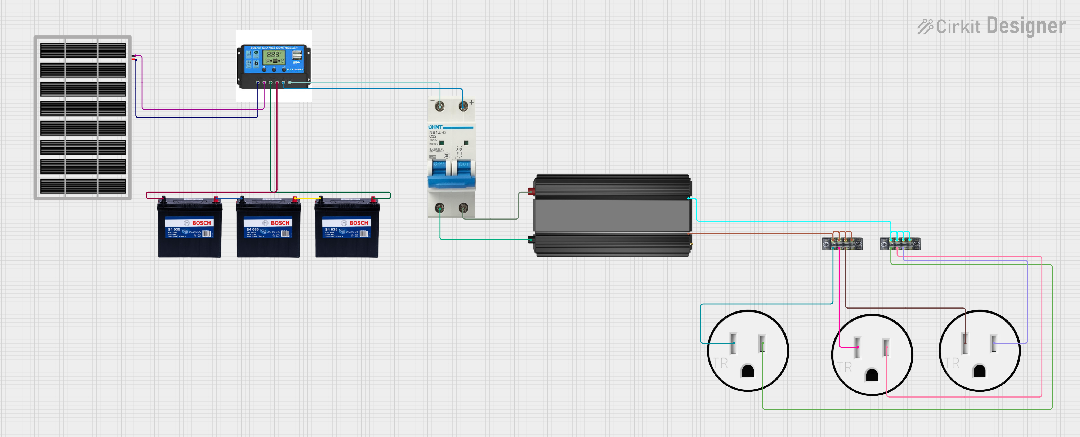
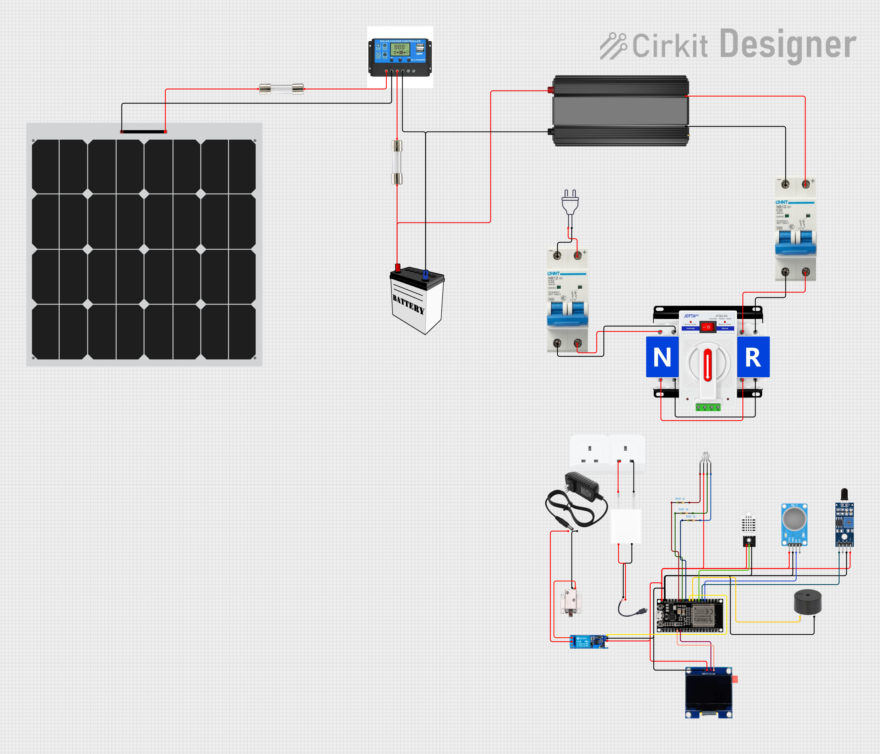
Explore Projects Built with 3P Breaker
Common Applications and Use Cases
- Protection of three-phase motors and machinery
- Distribution panel protection in industrial and commercial buildings
- Safeguarding HVAC systems and large electrical loads
- Ensuring safety in renewable energy systems (e.g., solar inverters)
- Use in power distribution networks for three-phase systems
Technical Specifications
Below are the key technical details and pin configuration for a typical 3P breaker:
Key Technical Details
| Parameter | Value/Range |
|---|---|
| Rated Voltage | 400V AC (typical for three-phase) |
| Rated Current | 10A to 125A (varies by model) |
| Breaking Capacity | 6kA to 50kA (depends on application) |
| Number of Poles | 3 |
| Frequency | 50Hz or 60Hz |
| Trip Mechanism | Thermal-magnetic or electronic |
| Operating Temperature | -20°C to 70°C |
| Mounting Type | DIN rail or panel-mounted |
Pin Configuration and Descriptions
The 3P breaker has three input terminals and three output terminals, corresponding to the three phases (L1, L2, L3). Below is the pin configuration:
| Terminal Label | Description |
|---|---|
| L1 (Input) | Phase 1 input terminal |
| L2 (Input) | Phase 2 input terminal |
| L3 (Input) | Phase 3 input terminal |
| L1 (Output) | Phase 1 output terminal |
| L2 (Output) | Phase 2 output terminal |
| L3 (Output) | Phase 3 output terminal |
Usage Instructions
How to Use the 3P Breaker in a Circuit
- Determine the Load Requirements: Identify the voltage, current, and breaking capacity required for your application. Select a 3P breaker that matches or exceeds these requirements.
- Connect the Input Terminals: Connect the three-phase power supply to the input terminals (L1, L2, L3) of the breaker.
- Connect the Output Terminals: Connect the load (e.g., motor, distribution panel) to the output terminals (L1, L2, L3).
- Secure the Breaker: Mount the breaker on a DIN rail or panel, ensuring it is firmly secured.
- Test the Circuit: After installation, test the circuit to ensure proper operation and that the breaker trips under fault conditions.
Important Considerations and Best Practices
- Select the Correct Rating: Always choose a breaker with a current rating and breaking capacity suitable for your application.
- Ensure Proper Wiring: Use appropriately rated cables for the input and output connections to prevent overheating or damage.
- Regular Maintenance: Periodically inspect the breaker for signs of wear, damage, or loose connections.
- Avoid Overloading: Do not exceed the rated current of the breaker to ensure reliable operation.
- Safety First: Always turn off the power supply before installing or servicing the breaker.
Example: Connecting a 3P Breaker to an Arduino UNO
While a 3P breaker is not directly connected to an Arduino UNO, you can use a current sensor (e.g., ACS712) to monitor the load current and control a relay to trip the breaker indirectly. Below is an example code snippet for monitoring current:
// Example code to monitor current using ACS712 and control a relay
// connected to an Arduino UNO. This can indirectly trip a 3P breaker.

#include <ACS712.h>

// Initialize ACS712 sensor (e.g., 30A version) on analog pin A0
ACS712 sensor(ACS712_30A, A0);

const int relayPin = 7; // Pin connected to the relay module
const float currentThreshold = 10.0; // Current threshold in amps

void setup() {
  Serial.begin(9600); // Initialize serial communication
  pinMode(relayPin, OUTPUT); // Set relay pin as output
  digitalWrite(relayPin, LOW); // Ensure relay is off initially
  sensor.calibrate(); // Calibrate the ACS712 sensor
}

void loop() {
  float current = sensor.getCurrentAC(); // Get the AC current reading
  Serial.print("Current: ");
  Serial.print(current);
  Serial.println(" A");

  // Check if current exceeds the threshold
  if (current > currentThreshold) {
    digitalWrite(relayPin, HIGH); // Activate relay to trip breaker
    Serial.println("Overcurrent detected! Relay activated.");
  } else {
    digitalWrite(relayPin, LOW); // Deactivate relay
  }

  delay(1000); // Wait for 1 second before next reading
}
Troubleshooting and FAQs
Common Issues and Solutions
| Issue | Possible Cause | Solution |
|---|---|---|
| Breaker trips frequently | Overloaded circuit | Reduce the load or use a higher-rated breaker. |
| Breaker does not trip during faults | Faulty trip mechanism | Replace the breaker or consult a technician. |
| Overheating of breaker | Loose connections or undersized cables | Tighten connections and use proper cables. |
| Difficulty in mounting | Incorrect mounting type | Verify the breaker is compatible with your panel or DIN rail. |
FAQs
Q: Can a 3P breaker be used for single-phase systems?
A: Yes, but it is not recommended as it is designed for three-phase systems. For single-phase systems, use a single-pole or double-pole breaker.
Q: How do I know if my breaker is faulty?
A: Signs of a faulty breaker include failure to trip during faults, physical damage, or unusual heating. Test the breaker or consult a professional.
Q: Can I reset a tripped 3P breaker?
A: Yes, after addressing the fault, you can reset the breaker by switching it back to the "ON" position. Ensure the fault is resolved before resetting.
Q: What is the difference between thermal-magnetic and electronic trip mechanisms?
A: Thermal-magnetic breakers use a bimetallic strip and magnetic coil for tripping, while electronic breakers use sensors and microprocessors for precise control.