
How to Use Analog Joystick (Wokwi Compatible): Examples, Pinouts, and Specs
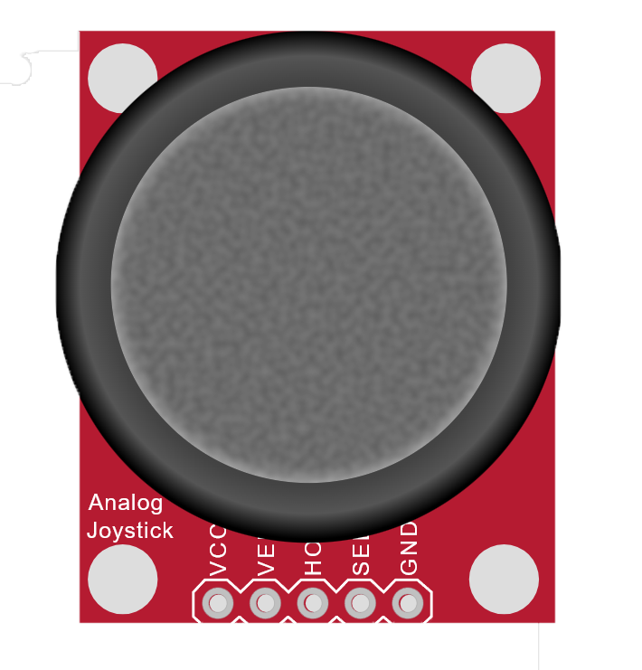
 Design with Analog Joystick (Wokwi Compatible) in Cirkit Designer
Introduction
The Analog Joystick is a two-axis input device that allows for directional control and variable resistance. It is commonly used in gaming controllers, robotics, and other applications requiring precise navigation or movement. The joystick features two potentiometers for the X and Y axes and a push-button for additional input functionality. Its compatibility with platforms like Wokwi and Arduino makes it a versatile and beginner-friendly component for prototyping and development.
Explore Projects Built with Analog Joystick (Wokwi Compatible)
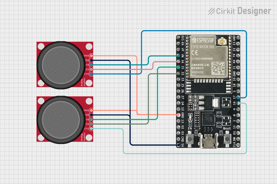 Open Project in Cirkit Designer
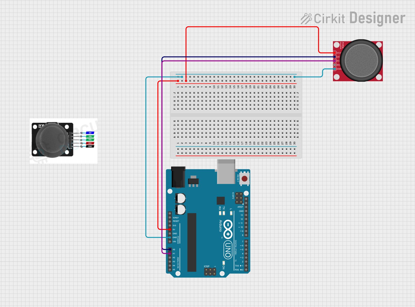 Open Project in Cirkit Designer
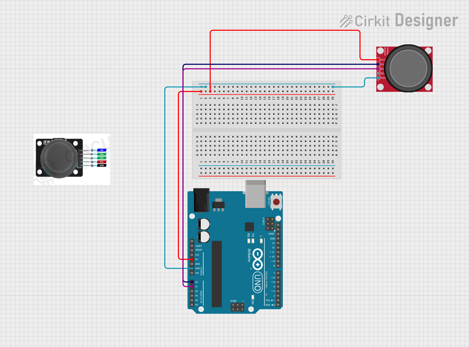 Open Project in Cirkit Designer
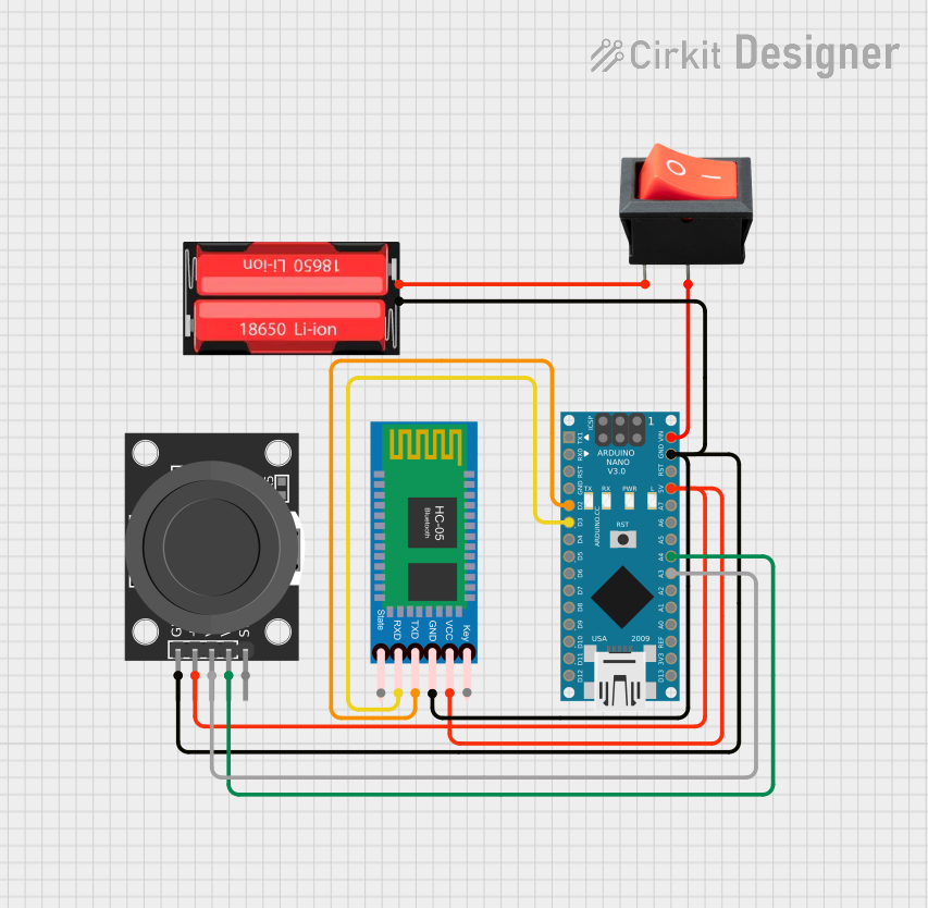 Open Project in Cirkit Designer
Explore Projects Built with Analog Joystick (Wokwi Compatible)
Open Project in Cirkit DesignerOpen Project in Cirkit DesignerOpen Project in Cirkit DesignerOpen Project in Cirkit DesignerCommon Applications
- Gaming controllers for directional input
- Robotic navigation and control
- Camera gimbal control
- DIY remote-controlled vehicles
- User interface navigation in embedded systems
Technical Specifications
The Analog Joystick consists of two potentiometers (for X and Y axes) and a tactile push-button. Below are the key technical details:
| Parameter | Specification |
|---|---|
| Operating Voltage | 3.3V - 5V |
| X-Axis Output Range | 0V - Vcc (Analog Output) |
| Y-Axis Output Range | 0V - Vcc (Analog Output) |
| Button Output | Digital (Active Low) |
| Dimensions | 40mm x 26mm x 32mm |
| Interface | Analog (X, Y), Digital (Button) |
Pin Configuration
The joystick typically has 5 pins. Below is the pinout description:
| Pin | Name | Description |
|---|---|---|
| 1 | GND | Ground connection |
| 2 | +Vcc | Power supply (3.3V or 5V) |
| 3 | VRx | X-axis analog output (connect to an ADC pin) |
| 4 | VRy | Y-axis analog output (connect to an ADC pin) |
| 5 | SW | Push-button digital output (active low) |
Usage Instructions
Connecting the Joystick
- Power Supply: Connect the
+Vccpin to a 3.3V or 5V power source and theGNDpin to ground. - X and Y Axes: Connect the
VRxandVRypins to analog input pins on your microcontroller (e.g., Arduino). - Push-Button: Connect the
SWpin to a digital input pin on your microcontroller. Use a pull-up resistor if necessary.
Example Circuit with Arduino UNO
Below is an example of how to connect the joystick to an Arduino UNO:
+Vcc→ 5VGND→ GNDVRx→ A0VRy→ A1SW→ D2
Sample Arduino Code
The following code reads the X and Y axis values and detects button presses:
// Define pin connections
const int VRxPin = A0; // X-axis analog pin
const int VRyPin = A1; // Y-axis analog pin
const int SWPin = 2;   // Push-button digital pin

void setup() {
  // Initialize serial communication for debugging
  Serial.begin(9600);

  // Configure the button pin as input with internal pull-up resistor
  pinMode(SWPin, INPUT_PULLUP);
}

void loop() {
  // Read X and Y axis values (0-1023 for 10-bit ADC)
  int xValue = analogRead(VRxPin);
  int yValue = analogRead(VRyPin);

  // Read the button state (LOW when pressed)
  bool buttonPressed = digitalRead(SWPin) == LOW;

  // Print the values to the Serial Monitor
  Serial.print("X: ");
  Serial.print(xValue);
  Serial.print(" | Y: ");
  Serial.print(yValue);
  Serial.print(" | Button: ");
  Serial.println(buttonPressed ? "Pressed" : "Released");

  // Add a small delay for stability
  delay(100);
}
Best Practices
- Use a stable power supply to avoid noise in the analog readings.
- Calibrate the joystick's center position (typically around 512 for a 10-bit ADC).
- Debounce the push-button in software if it is used for critical input.
Troubleshooting and FAQs
Common Issues
No Output or Incorrect Readings
- Cause: Loose or incorrect wiring.
- Solution: Double-check all connections and ensure the joystick is powered correctly.
Analog Values Fluctuate
- Cause: Electrical noise or unstable power supply.
- Solution: Use decoupling capacitors near the power pins or a regulated power source.
Button Not Detected
- Cause: Missing pull-up resistor or incorrect pin configuration.
- Solution: Enable the internal pull-up resistor in your microcontroller or add an external one.
FAQs
Q: Can I use the joystick with a 3.3V microcontroller?
A: Yes, the joystick is compatible with both 3.3V and 5V systems.
Q: How do I calibrate the joystick?
A: Read the X and Y axis values when the joystick is at rest. Use these values as the center point in your code.
Q: Is the push-button necessary for operation?
A: No, the push-button is optional and can be left unconnected if not needed.
Q: Can I use this joystick with platforms like Wokwi?
A: Yes, the joystick is fully compatible with Wokwi for virtual prototyping and simulation.