How to Use Traffic Light: Examples, Pinouts, and Specs
Introduction
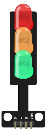
A traffic light is a signaling device that uses colored lights—red, yellow, and green—to control traffic flow at intersections. The red light signals vehicles to stop, the yellow light indicates caution and prepares drivers to stop, and the green light allows vehicles to proceed. Traffic lights are essential for maintaining order and safety on roads and are widely used in urban and suburban areas.
Explore Projects Built with Traffic Light
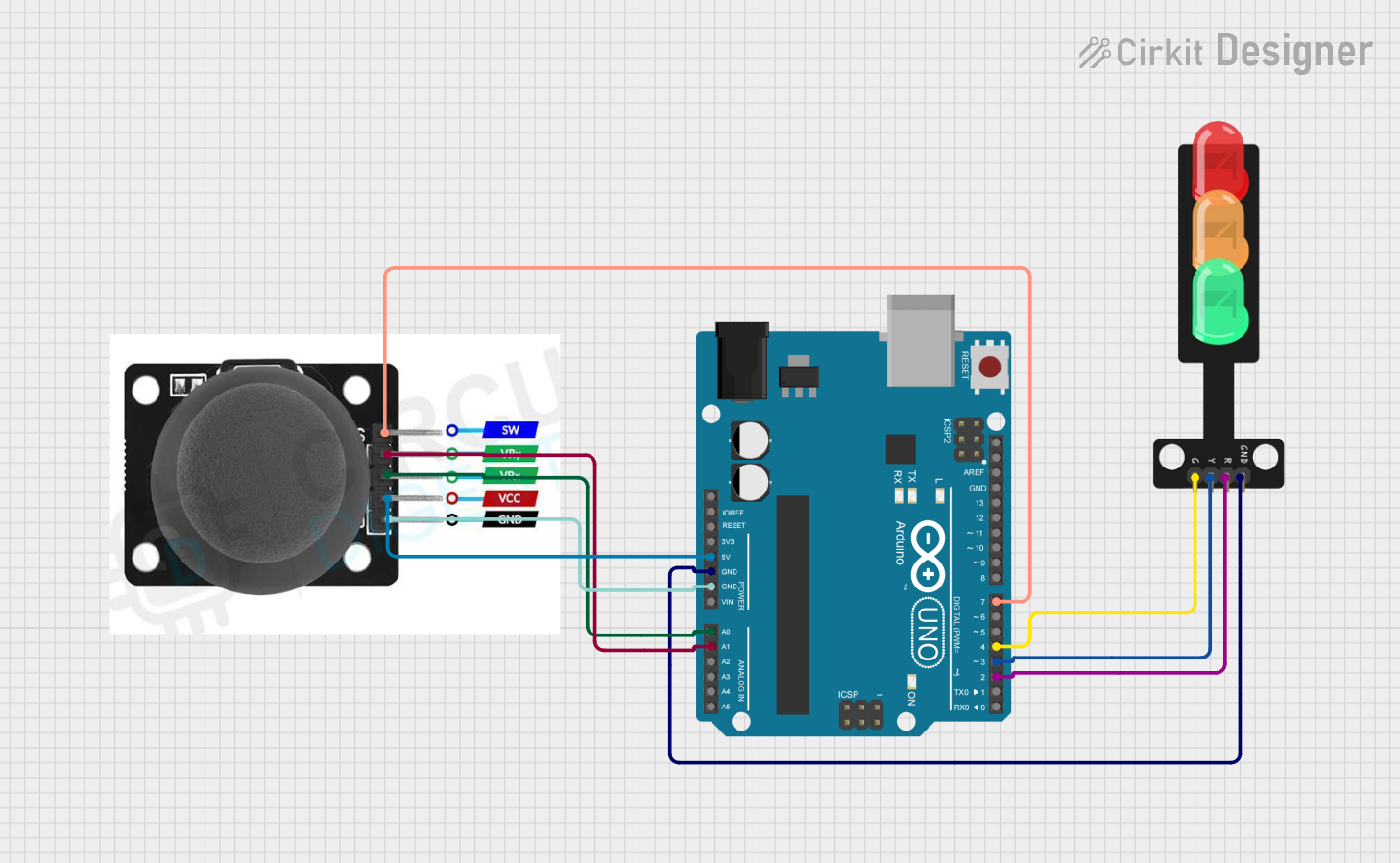
Explore Projects Built with Traffic Light
Common Applications and Use Cases
- Traffic control at road intersections
- Pedestrian crossings
- Simulated traffic systems for educational purposes
- Embedded systems and IoT projects
- Robotics and automation projects
Technical Specifications
Below are the general technical specifications for a standard traffic light module used in electronics projects:
| Parameter | Value |
|---|---|
| Operating Voltage | 5V DC |
| Current Consumption | ~20mA per LED |
| LED Colors | Red, Yellow, Green |
| LED Type | 5mm or 10mm diffused LEDs |
| Control Pins | 3 (one for each LED) |
| Module Dimensions | ~30mm x 70mm |
Pin Configuration and Descriptions
The traffic light module typically has three pins for controlling the LEDs. Below is the pin configuration:
| Pin | Name | Description |
|---|---|---|
| 1 | Red LED | Controls the red LED (stop signal) |
| 2 | Yellow LED | Controls the yellow LED (caution signal) |
| 3 | Green LED | Controls the green LED (go signal) |
| 4 | GND | Ground connection for the module |
| 5 | VCC | Power supply input (5V DC) |
Usage Instructions
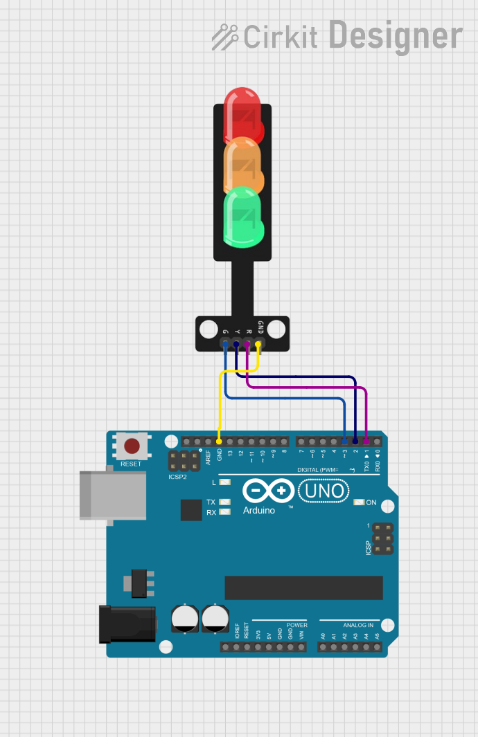
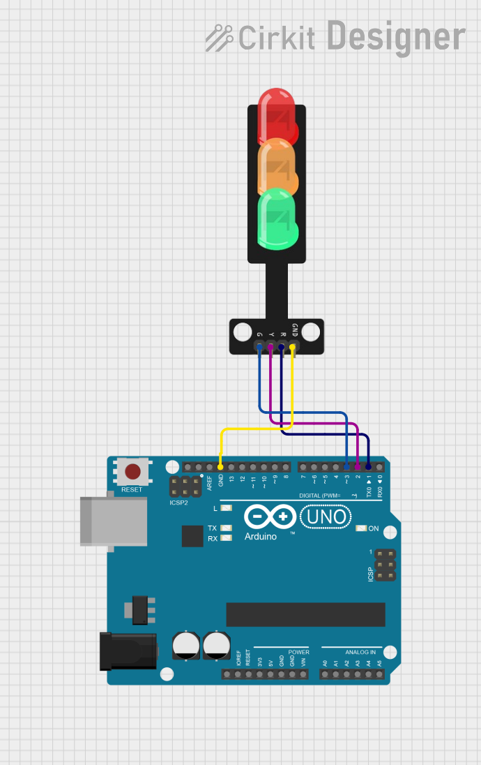
How to Use the Component in a Circuit
- Power the Module: Connect the VCC pin to a 5V DC power source and the GND pin to the ground.
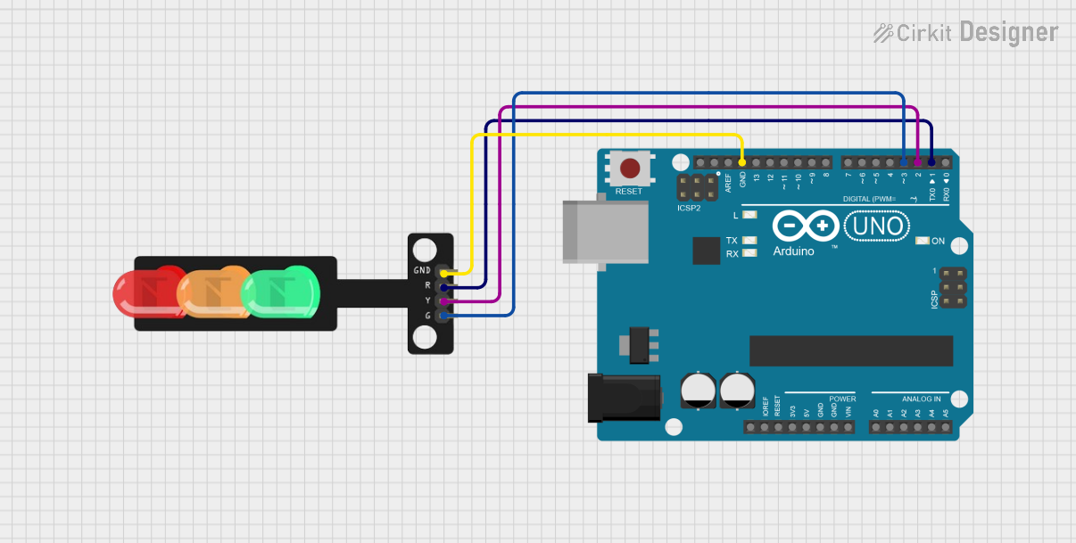
- Control the LEDs: Use a microcontroller (e.g., Arduino UNO) or switches to control the Red, Yellow, and Green LEDs by applying HIGH or LOW signals to their respective pins.
- Resistors: If the module does not include built-in resistors, connect a 220Ω resistor in series with each LED to limit the current and prevent damage.
Important Considerations and Best Practices
- Power Supply: Ensure the module is powered with a stable 5V DC supply to avoid flickering or damage.
- Current Limiting: Always use appropriate resistors if the module does not have built-in current-limiting resistors.
- Timing: When simulating a real traffic light, use appropriate delays between light transitions (e.g., 5 seconds for green, 2 seconds for yellow, and 5 seconds for red).
- Polarity: Double-check the polarity of the connections to avoid damaging the LEDs.
Example Code for Arduino UNO
Below is an example Arduino sketch to control a traffic light module:
// Pin definitions for the traffic light module
const int redPin = 2;    // Red LED connected to digital pin 2
const int yellowPin = 3; // Yellow LED connected to digital pin 3
const int greenPin = 4;  // Green LED connected to digital pin 4

void setup() {
  // Set the LED pins as outputs
  pinMode(redPin, OUTPUT);
  pinMode(yellowPin, OUTPUT);
  pinMode(greenPin, OUTPUT);
}

void loop() {
  // Turn on the green light for 5 seconds
  digitalWrite(greenPin, HIGH);
  delay(5000); // Wait for 5 seconds
  digitalWrite(greenPin, LOW);

  // Turn on the yellow light for 2 seconds
  digitalWrite(yellowPin, HIGH);
  delay(2000); // Wait for 2 seconds
  digitalWrite(yellowPin, LOW);

  // Turn on the red light for 5 seconds
  digitalWrite(redPin, HIGH);
  delay(5000); // Wait for 5 seconds
  digitalWrite(redPin, LOW);
}
Troubleshooting and FAQs
Common Issues Users Might Face
LEDs Not Lighting Up:
- Check the power supply and ensure the module is receiving 5V DC.
- Verify the connections and ensure the pins are correctly connected to the microcontroller or power source.
- If using external resistors, ensure they are of the correct value (e.g., 220Ω).
Flickering LEDs:
- Ensure the power supply is stable and not fluctuating.
- Check for loose connections or poor soldering on the module.
Incorrect LED Behavior:
- Verify the code logic if using a microcontroller.
- Double-check the pin assignments in the code and ensure they match the physical connections.
Solutions and Tips for Troubleshooting
- Use a multimeter to check the voltage at the VCC and GND pins.
- Test each LED individually by connecting it directly to a power source with a resistor.
- If the module is not working as expected, try replacing it with a new one to rule out hardware defects.
By following this documentation, you can effectively use a traffic light module in your projects and troubleshoot common issues with ease.