How to Use 4 Relay Module: Examples, Pinouts, and Specs
UMLIFE 4 Relay Module Documentation
1. Introduction
The UMLIFE 4 Relay Module is a versatile electronic component designed to control high-voltage devices using low-voltage signals. It features four independent relays, each capable of switching AC or DC loads. This module is widely used in home automation, industrial control systems, robotics, and IoT applications. Its ability to interface with microcontrollers like Arduino, Raspberry Pi, and other development boards makes it a popular choice for hobbyists and professionals alike.
Common Applications:
- Home automation (e.g., controlling lights, fans, or appliances)
- Industrial equipment control
- Robotics (e.g., motor or actuator control)
- IoT systems for remote device management
- Security systems (e.g., activating alarms or locks)
2. Technical Specifications
The UMLIFE 4 Relay Module is designed for reliable and efficient operation. Below are its key technical details:
General Specifications:
| Parameter | Value |
|---|---|
| Operating Voltage | 5V DC |
| Trigger Voltage | 3.3V - 5V DC |
| Relay Type | Electromechanical SPDT (Single Pole Double Throw) |
| Maximum Load (AC) | 250V AC @ 10A |
| Maximum Load (DC) | 30V DC @ 10A |
| Isolation | Optocoupler isolation for each relay |
| Dimensions | 75mm x 55mm x 20mm |
| Weight | ~60g |
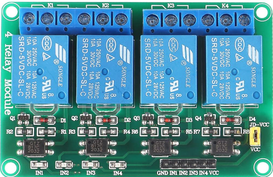
Pin Configuration:
The module has a total of 10 pins for input and output connections. Below is the pin description:
| Pin Name | Type | Description |
|---|---|---|
| VCC | Power Input | Connect to 5V DC power supply. |
| GND | Ground | Connect to the ground of the power supply. |
| IN1 | Control Signal | Trigger input for Relay 1 (Active LOW). |
| IN2 | Control Signal | Trigger input for Relay 2 (Active LOW). |
| IN3 | Control Signal | Trigger input for Relay 3 (Active LOW). |
| IN4 | Control Signal | Trigger input for Relay 4 (Active LOW). |
| COM1 | Load Terminal | Common terminal for Relay 1. |
| NO1 | Load Terminal | Normally Open terminal for Relay 1. |
| NC1 | Load Terminal | Normally Closed terminal for Relay 1. |
| (Repeat for Relays 2, 3, and 4) |
3. Usage Instructions
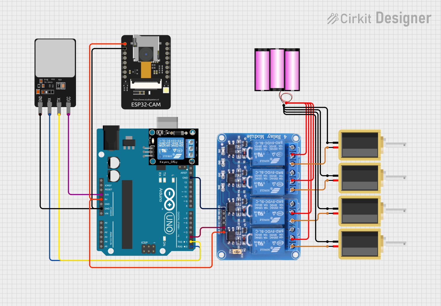
Connecting the 4 Relay Module:
Power Supply:
- Connect the
VCCpin to a 5V DC power source. - Connect the
GNDpin to the ground of the same power source.
- Connect the
Control Signals:
- Connect the
IN1,IN2,IN3, andIN4pins to the digital output pins of a microcontroller (e.g., Arduino). - The relays are active LOW, meaning they will activate when the control pin is set to LOW.
- Connect the
Load Connections:
- Each relay has three terminals:
COM,NO, andNC.COM(Common): Connect to the power source or load.NO(Normally Open): The load is connected here if you want it to be OFF by default and ON when the relay is activated.NC(Normally Closed): The load is connected here if you want it to be ON by default and OFF when the relay is activated.
- Each relay has three terminals:
Example Circuit:
- Connect a 220V AC light bulb to
COM1andNO1of Relay 1. - Use an Arduino to control the relay via the
IN1pin.
Arduino Code Example:
Below is an example code to control the 4 Relay Module using an Arduino UNO:
// Example: Controlling a 4 Relay Module with Arduino UNO
// Ensure the relay module is connected to 5V and GND on the Arduino.
// IN1, IN2, IN3, and IN4 are connected to digital pins 7, 6, 5, and 4 respectively.

#define RELAY1 7  // Pin connected to IN1
#define RELAY2 6  // Pin connected to IN2
#define RELAY3 5  // Pin connected to IN3
#define RELAY4 4  // Pin connected to IN4

void setup() {
  // Set relay pins as OUTPUT
  pinMode(RELAY1, OUTPUT);
  pinMode(RELAY2, OUTPUT);
  pinMode(RELAY3, OUTPUT);
  pinMode(RELAY4, OUTPUT);

  // Initialize all relays to OFF (HIGH state)
  digitalWrite(RELAY1, HIGH);
  digitalWrite(RELAY2, HIGH);
  digitalWrite(RELAY3, HIGH);
  digitalWrite(RELAY4, HIGH);
}

void loop() {
  // Turn on Relay 1
  digitalWrite(RELAY1, LOW);  // Activate Relay 1
  delay(1000);                // Wait for 1 second

  // Turn off Relay 1 and turn on Relay 2
  digitalWrite(RELAY1, HIGH); // Deactivate Relay 1
  digitalWrite(RELAY2, LOW);  // Activate Relay 2
  delay(1000);                // Wait for 1 second

  // Turn off Relay 2 and turn on Relay 3
  digitalWrite(RELAY2, HIGH); // Deactivate Relay 2
  digitalWrite(RELAY3, LOW);  // Activate Relay 3
  delay(1000);                // Wait for 1 second

  // Turn off Relay 3 and turn on Relay 4
  digitalWrite(RELAY3, HIGH); // Deactivate Relay 3
  digitalWrite(RELAY4, LOW);  // Activate Relay 4
  delay(1000);                // Wait for 1 second

  // Turn off all relays
  digitalWrite(RELAY4, HIGH); // Deactivate Relay 4
  delay(1000);                // Wait for 1 second
}
4. Troubleshooting and FAQs
Common Issues:
Relays not activating:
- Ensure the module is powered with 5V DC.
- Verify that the control signals are correctly connected and set to LOW to activate the relays.
Load not switching:
- Check the wiring of the load to the
COM,NO, andNCterminals. - Ensure the load does not exceed the relay's maximum current and voltage ratings.
- Check the wiring of the load to the
Module overheating:
- Avoid exceeding the maximum load ratings of the relays.
- Ensure proper ventilation around the module.
FAQs:
Q1: Can I use the module with a 3.3V microcontroller?
A1: Yes, the module is compatible with 3.3V control signals due to its optocoupler isolation.
Q2: Can I control DC motors with this module?
A2: Yes, you can control DC motors as long as their voltage and current ratings are within the relay's limits.
Q3: Is the module safe for high-voltage applications?
A3: Yes, but ensure proper insulation and safety precautions when working with high-voltage AC loads.
5. Safety Precautions
- Always disconnect power before wiring the module.
- Avoid touching the module when it is connected to high-voltage loads.
- Use proper insulation and enclosures for high-voltage applications.
- Ensure the load does not exceed the relay's maximum ratings to prevent damage.
This documentation provides a comprehensive guide to using the UMLIFE 4 Relay Module effectively. For further assistance, refer to the manufacturer's datasheet or contact technical support.
Explore Projects Built with 4 Relay Module


Explore Projects Built with 4 Relay Module